Chapter 8 HYBRID Coater Service Manual ver1.1
56
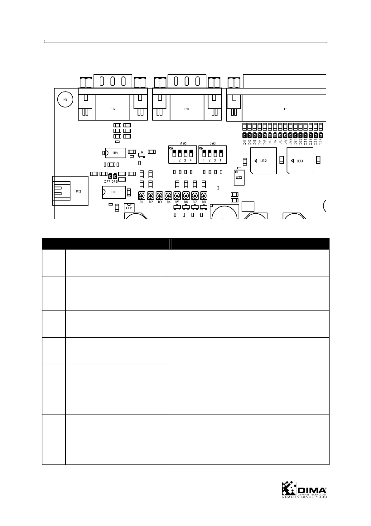
8.2.1 LED’s on Upper Left Side of the EL-04873
LED Used for State
D1 24Volt indication Must be ON! Otherwise check fuses and power.
This 24Volt is used for all inputs and outputs of this
PCB.
D2 15Volt indication Must be ON! If LED’s D2, D3 and D4 are OFF
check fuses and power, otherwise EL-04873 is
probably defective. This 15Volt is used for the 0-
10Volt outputs and the CAN-interface.
D3 5Volt indication Must be ON! If LED’s D2, D3 and D4 are OFF
check fuses and power, otherwise EL-04873 is
probably defective.
D4 3.3Volt indication Must be ON! If LED’s D2, D3 and D4 are OFF
check fuses and power, otherwise EL-04873 is
probably defective.
D5 Command received Each time a command is received (via USB or
RS232) this LED changes state. During normal
operation this LED continuously changes state.
When the LED stays in the same state, the USB or
RS232 cable may be loose or the controller is
performing no action.
D6 Command sent Each time a command is transmitted (via USB or
RS232) this LED changes state. During normal
operation this LED continuously changes state.
When the LED stays in the same state, the USB or
RS232 cable may be loose or the controller is
performing no action.