Replacing the Timing Board
4-68 72A-1230 Rev. F
July 22, 2005
Replacing the Timing Board
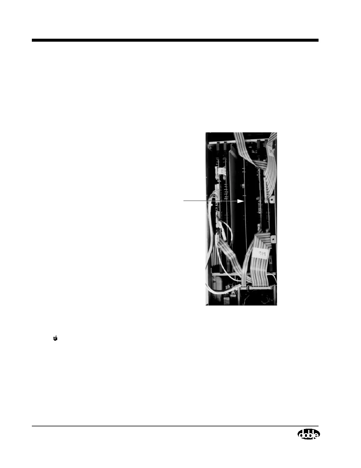
Note the location of the Timing Board in Figure 4.24 on page 4-49 and in
Figure 4.35 below. Take the following steps to replace it:
1. If it has not already been done, remove the card cage cover. See
”Removing the Card Cage Cover” on page 4-48. The Timing Board will
be visible as in Figure 4.35.
Figure 4.35 Timing Board
NOTE Do not remove the replacement board from its anti-static bag until
instructed to do so. See the Note on page 4-48 for additional ESD
precautions.
2. Use your index fingers to unlatch both PC board extractors. Then, pull the
board straight up.
3. Remove the replacement Timing Board from its anti-static bag and guide
it into position. Press down evenly on the insides of the PC extractors until
the board is firmly seated.
connectors, lowvolt. power supply
Timing Board