Operating Procedure of Type C Resonating Inductor
3-26 72A-1230 Rev. F
July 22, 2005
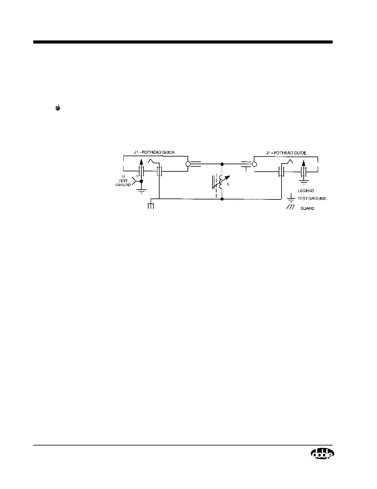
The Resonator, shown schematically in Figure 3.18, is contained in a metal
housing measuring 24 x 17 x 15 inches, and weighs approximately 185
pounds.
NOTE L adjustable from 7 to 140 Henries @60Hz.
Counter dial calibrated per calibration chart supplied with each unit.
Resonator chassis ground connected to test ground through cable shield
or external test ground lead.
Figure 3.18 Schematic of Type C Resonating Inductor
Operating Procedure of Type C Resonating Inductor
The Resonator is connected to the M4100 Instrument by means of an 8-ft,10
kV jumper cable. The regular 10 kV test cable is connected between the
Resonator and the test specimen. Cable receptacles will be found in the rear of
the Resonator case and can be used interchangeably (see Figure 3.18).
The Resonator is equipped with a core-clamping arrangement to reduce the
noise level when the Resonator is in use, and more importantly, to minimize
vibration. A speeder-type wrench is provided for use with this clamping
arrangement and for use in tuning the Resonator. The clamping adjustment is
located in the front vertical face of the Resonator while the tuning control is
located in the top panel. Turning the clamping adjustment approximately 180°
counterclockwise or clockwise will either unclamp or clamp the core,
respectively.
If the equivalent 10 kV charging current of the test specimen is known, the
Resonator may be set approximately by adjusting the tuning control until the
counter setting corresponds to this current. Mounted on the Resonator panel is
a reference chart relating the approximate counter reading to the specimen
current.