Replacing the Main Reference Assembly
4-74 72A-1230 Rev. F
July 22, 2005
Replacing the Main Reference Assembly
Note the location of the Main Reference Assembly in Figure 4.30
on page 4-60. Take the following steps to replace it:
1. If it has not already been done, remove the Front Panel Assembly. See
Steps 1-8, ”Removing and Replacing the Front Panel Assembly”
on page 4-58. (The Front Panel Assembly must be removed to replace the
Main Reference Assembly, but the two assemblies are not attached.)
NOTE Do not remove the replacement board from its anti-static bag until
instructed to do so. See the Note on page 4-48 for additional ESD
precautions.
2. Remove the cover of the Main Reference Assembly. Do this by removing
the two screws using a Phillips-head screwdriver.
Removing one screw releases an orange cable.
3. Disconnect the W12 ribbon cable.
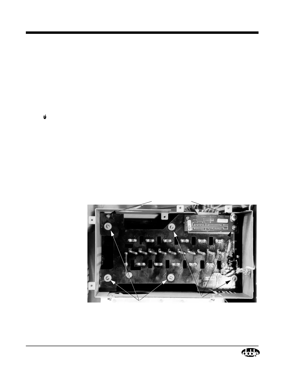
4. Remove two screws, one in each front corner of the Main Reference
Assembly (Figure 4.38), using a Phillips-head screwdriver. Some older
units have three screws to be removed.
.
Figure 4.38 Main Reference Assembly, Screw Locations
Front Screws
Perimeter Screws and Washers