Replacing the Guard Board
4-76 72A-1230 Rev. F
July 22, 2005
Replacing the Guard Board
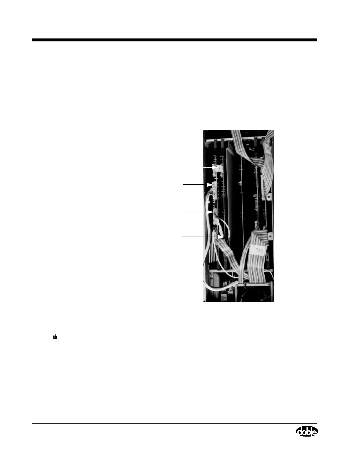
Note the location of the Guard Board in Figure 4.24 on page 4-49 and in
Figure 4.39 below. Take the following steps to replace it:
1. If it has not already been done, remove the card cage cover. See
”Removing the Card Cage Cover” on page 4-48. The Guard Board will be
visible as in Figure 4.39.
Figure 4.39 Guard Board
NOTE Do not remove the replacement board from its anti-static bag until
instructed to do so. See the Note on page 4-48 for additional ESD
precautions.
2. Detach the ribbon cable (W8) from the board.
3. Detach the two connectors on cable W9 from the board.
4. Use your index fingers to unlatch both PC board extractors. Then, pull the
board straight up.
connectors, lowvolt. power supply
Guard Board
W8 Connector
W11 Connector
W9 Connector