Replacing the I/O Protection Board
4-84 72A-1230 Rev. F
July 22, 2005
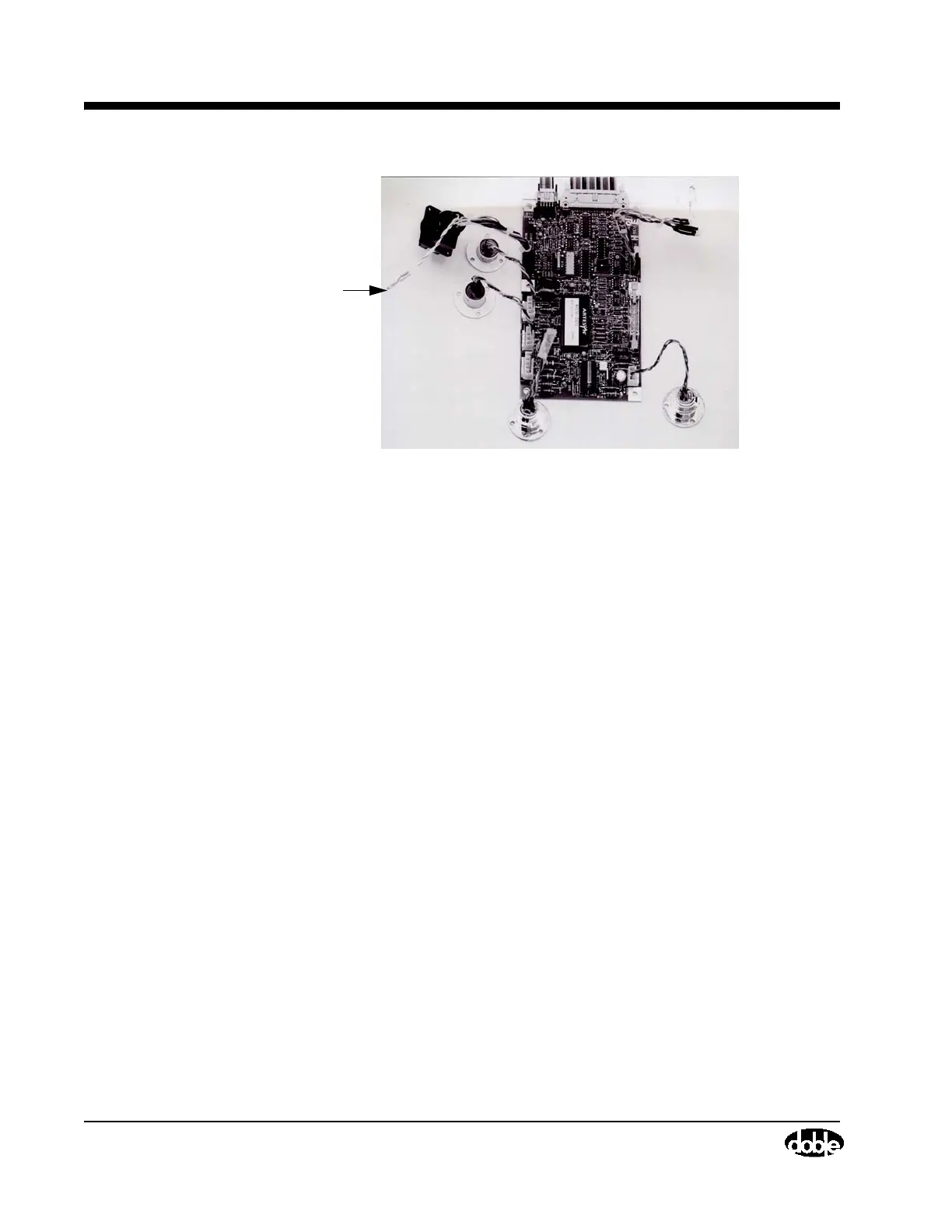
Figure 4.44 I/O Protection Board, Cable Connections
5. Carefully lift the I/O Protection Board off the Front Panel Assembly.
6. Unpack the replacement I/O Protection Board from its anti-static bag and
place the new board onto the Front Panel Assembly.
7. Replace six screws that attach the I/O Protection Board to the Front Panel
Assembly using a Phillips-head screwdriver.
• First replace the two middle screws (rather than the screws located in
the corners) to tack the board in place.
• Before replacing the screw that secures the grounding wire, first insert
the black and white wire between the I/O Protection Board and the
standoff. Then, tighten the screw.
8. Reconnect one W21 and two W24 ribbon cables. The W24 cable located
closest to the Field Calibration Reference connects to J2. The other W24
cable, located furthest away from the Field Calibration Reference,
connects to J3.
9. Reconnect four cables as follows:
•W22 to J7
•W23 to J9
•W25 to J1
•W26 to J4
10. Replace the Front Panel Assembly by following steps 9-14, ”Removing
and Replacing the Front Panel Assembly” on page 4-58.
11. Replace the top and front covers by reversing the steps in ”Removing the
Front and Top Covers” on page 4-46.
Ground
to
Upper
Left
Standoff