SECTION 6 Field Replaceable Parts
6–38 0855855eng 6/08
4. To replace the thermistor, reverse steps 1 through 3 above.
NOTE: Be careful plugging the connector into the backplane,
as it is possible to plug one pitch position off.
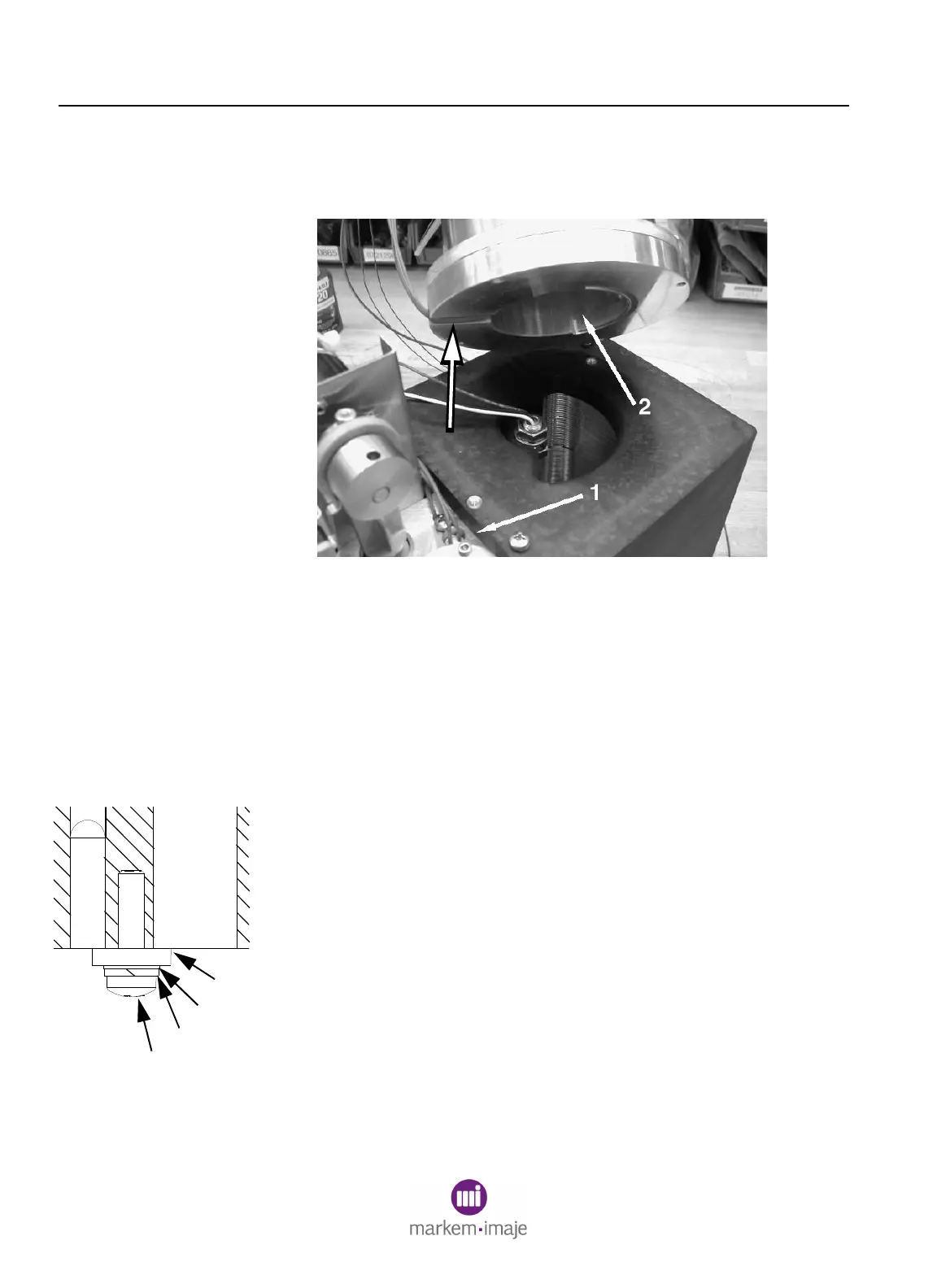
Figure 6–27
17.3.2 Melt Chamber Thermistor
1. Remove the ink delivery module. See Section 6, Replacing
the Ink Delivery Module and the Ink Delivery Module parts
illustration.
2. Disassemble the melt chamber from the heat shield by
removing the two screws.
3. Remove the screw (1), split washer (2), flat washer (3), and
thermostat (4) trapping the melt chamber thermistor (5) and
cartridge heater (6) and slide the thermistor out.
4. Disconnect the thermistor wires from positions #1 and #2 of the
green 12-position plug. Refer to Figure 6-9 and Table 6-1.
5. To replace the thermistor, reverse steps 1 through 4 above,
retaining the stacking order of the screws and washers. Make
sure there are no wires pinched between the melt chamber
assembly and the heat shield (3, Figure 6-27).
NOTE: Be careful plugging the connector into the backplane,
as it is possible to plug one pitch position off.
1
2
3
4
6
5

 Loading...