5 Function blocks
5.9 CI, High-speed incremental value counter
Control Relay easy800 11/11 MN04902001Z-EN www.eaton.com 177
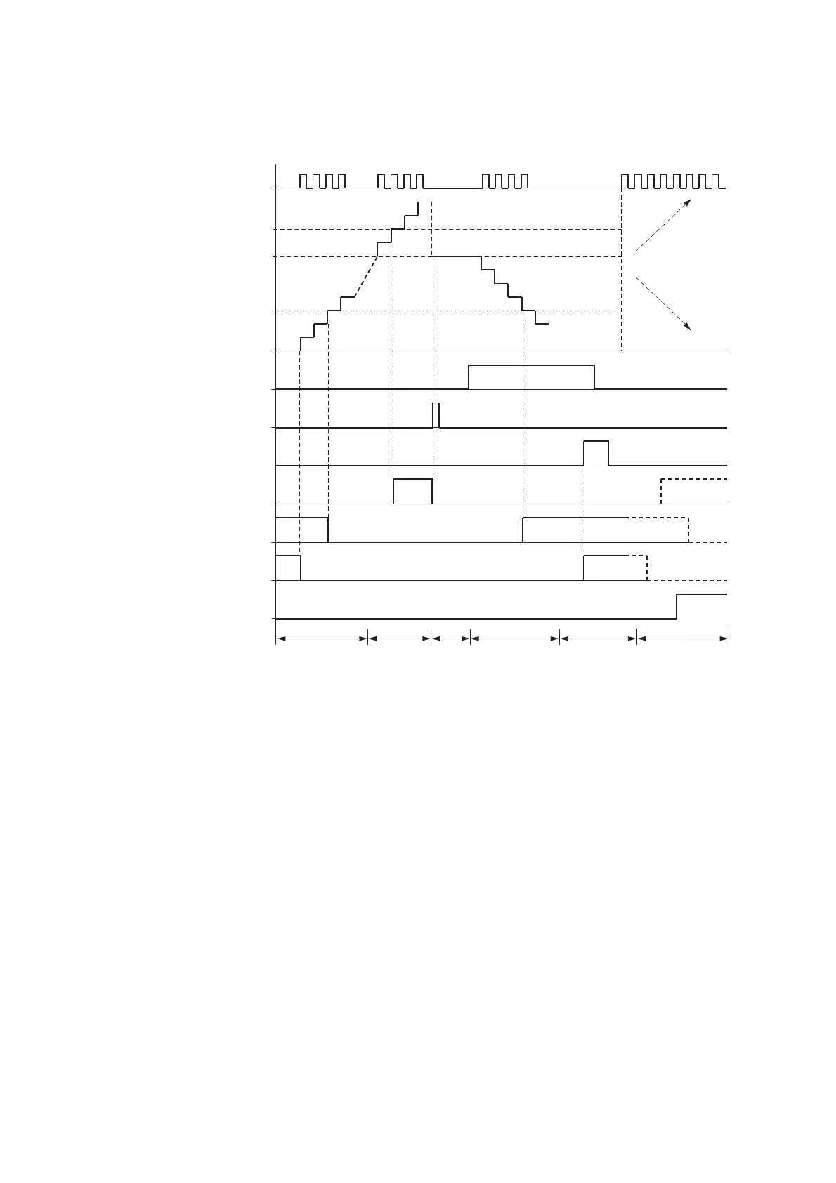
Figure 121:Signal diagram High-speed incremental value counter
1: Counter input I1 to I4.
2: Upper setpoint value SH.
3: Start value SV.
4: Lower setpoint value SL.
5: Counting direction, coil CI…D
6: Transfer start value, coil CI..SE.
7: Reset coil CI…RE
8: Contact (N/O) CI…OF: Upper setpoint value reached or exceeded.
9: Contact (N/O) CI…FB: Lower setpoint value reached or undershot.
10: Contact (N/O) CI…ZE: Actual value equal to zero
11:Out of value range.
• Range A:
– The counter has the value zero.
– The contacts CI..ZE (actual value = zero) and CI..FB (lower setpoint value undershot) are active.
– The counter receives pulses and increases the actual value.
– CI..ZE drops out as well as CI..FB and also when the lower setpoint value is reached.
• Range B:
– The counter counts upwards and reaches the upper setpoint value.
The “upper setpoint value reached” contact CI..OF becomes active.
• Range C:
– The coil CI..SE is briefly actuated and the actual value is set to the start value.
The contacts go to the respective position.
1
2
......... .........
3
4
6
7
8
9
10
11
ABCD E F
5
. . . . . . .

 Loading...


