2 Installation
2.5 Connecting the inputs
Control Relay easy800 11/11 MN04902001Z-EN www.eaton.com 41
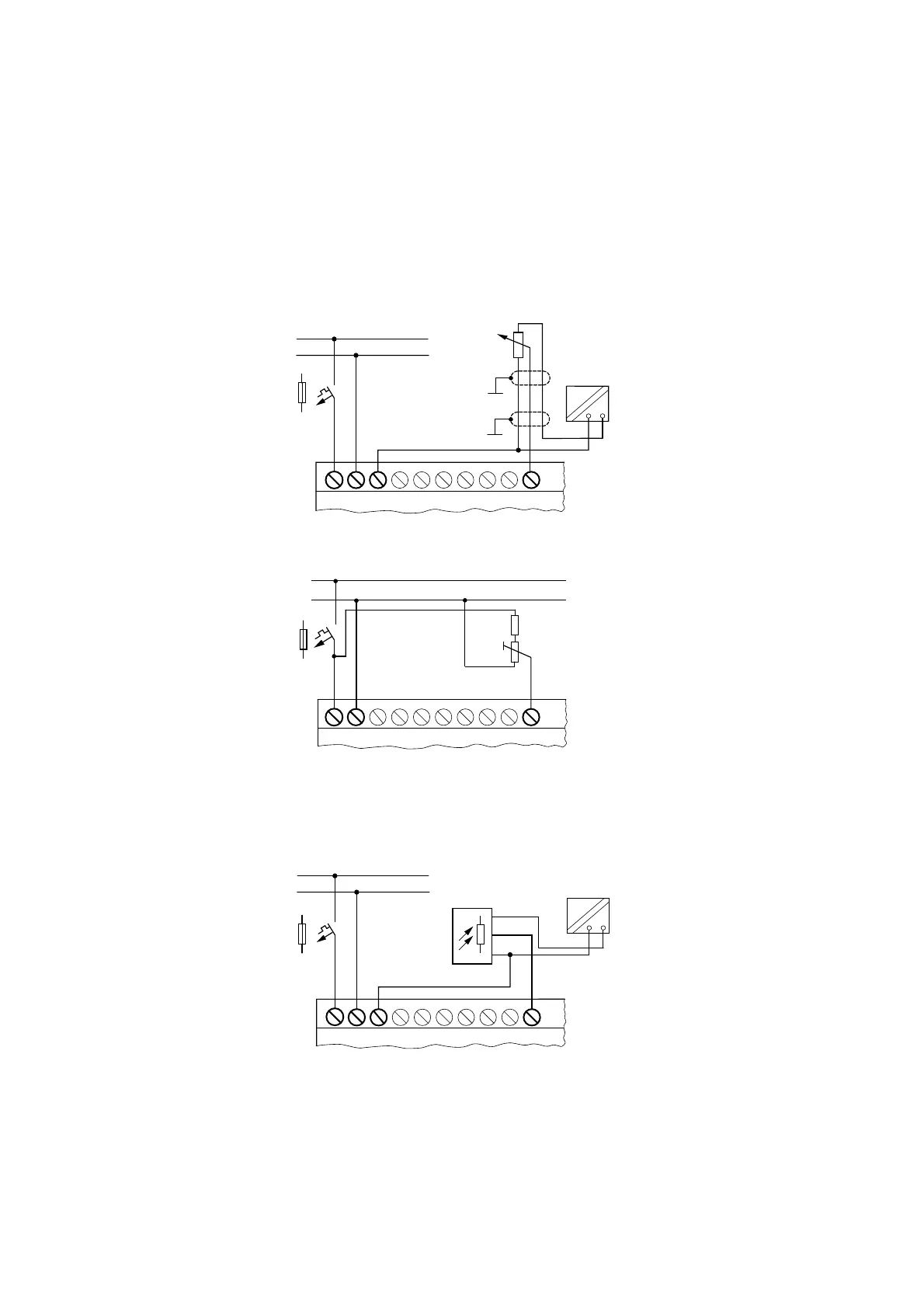
Setpoint potentiometer
Figure 38:Setpoint potentiometer
Figure 39:Setpoint potentiometer with upstream resistor
Use a potentiometer with the resistance ≤ 1kΩ e.g. 1 kΩ, 0.25 W.
Brightness sensor
Figure 40:Brightness sensor
→
Ensure that the reference potential is galvanically connected.
Connect the 0 V of the power supply unit for the different
setpoint potentiometers and sensors shown in the examples to
the 0 V terminal of the easy800 standard power supply.

 Loading...


