Function of CI 3000
24
Version 2.09 09. April 2014
4.4 CAN bus station monitoring
The CI 3000 Store Computer performs cyclic check on presence of all LDS components previously detected in
the system. Failure of a component is detected by station monitoring and generates a Computer Fault alarm.
Every new LDS component connected to the CAN bus is detected via “plug and play” automatically by the store
computer and included in station monitoring (Screen 7-1).
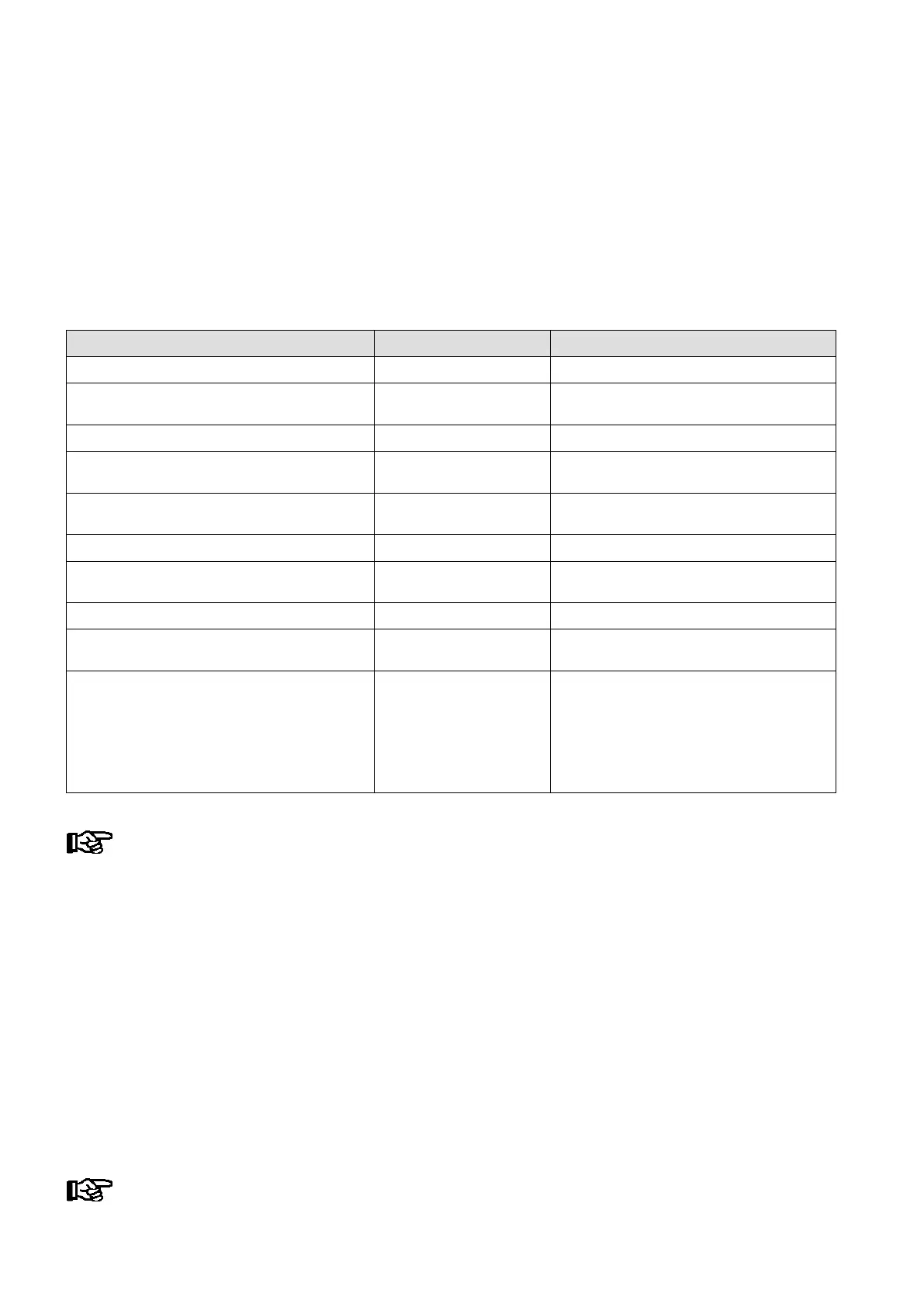
The following CAN bus nodes can be present in the LDS system:
LDS components CAN bus address Max. no. of LDS components on CAN bus
Case controller of the UA 300 and UA 400 series 1..99 99
VS 3010 / VS 3010 BS / VS 3010 CT / VS 3010 WP
FS 3010 / VS 300 / VS 3010 C pack controllers
101..109 9
CI 3000 Store Computer 111 (fixed address) 1
AL 300 Operator Terminal 112 .. 116, 117 .. 120 Max. 9 or max. 5, if 4 receiver modules are
present in the system.
Receiver module WR 300
for wireless temperature sensors TS 30 W
117 .. 120 4 (only possible, if NO operator terminal
uses these CAN bus addresses)
LDSWin PC via COM port 121 (fixed address) 1
DDC modules of building control system (BCS) 122..125 Maximum of 4 if there are no Modbus TCP
master gateways installed in the system
LDSWin PC via CAN bus PC adapter 126 (fixed address) 1
LDSWin PC via LAN gateway
(from version 1.1c or higher)
126 or 127 1
Combi-Gateway
- LAN-Gateway
- XML-Gateway
- Modbus TCP-Master 1 Gateway
- Modbus TCP-Master 2 Gateway
- Modbus TCP-Master 3 Gateway
- Modbus TCP-Master 4 Gateway
126 oder 127
110
122
123
124
125
1
1
Maximum of 4 if there are no DDC modules
installed in the system.
In failure or shutdown of the CI 3000 Store Computer, the AL 300 Operator Terminal having the low
est CAN bus address (when used) performs monitoring for the duration of the outage.
4.5 Alarm suppression in manual shutdown of LDS components
Shutdown of an LDS component is detected by CAN station monitoring as a failure (Screen 7-1). This causes a
prompt to appear on the display of the CI 3000 Store Computer and all AL 300 Operator Terminals (when used)
asking whether the LDS component has been shut down intentionally.
The user can then confirm shutdown within 5 minutes by pressing ENTER. If confirmation is made within this
interval, monitoring of the LDS component concerned will be deactivated and accordingly it will not be reported
as failed.
Otherwise, or if the user answers no to the prompt by pressing the ESC key, the LDS component will as normal
be reported as failed. An LDS component that has been shut down is automatically re-included in station moni
toring when it is switched on again.
The manual shutdown of case controllers is entered in the store computer’s message list!