Pin and Terminal Assignments of CI 3000 / SIOX
57
Version 2.09 09. April 2014
6 Pin and Terminal Assignments of CI 3000 / SIOX
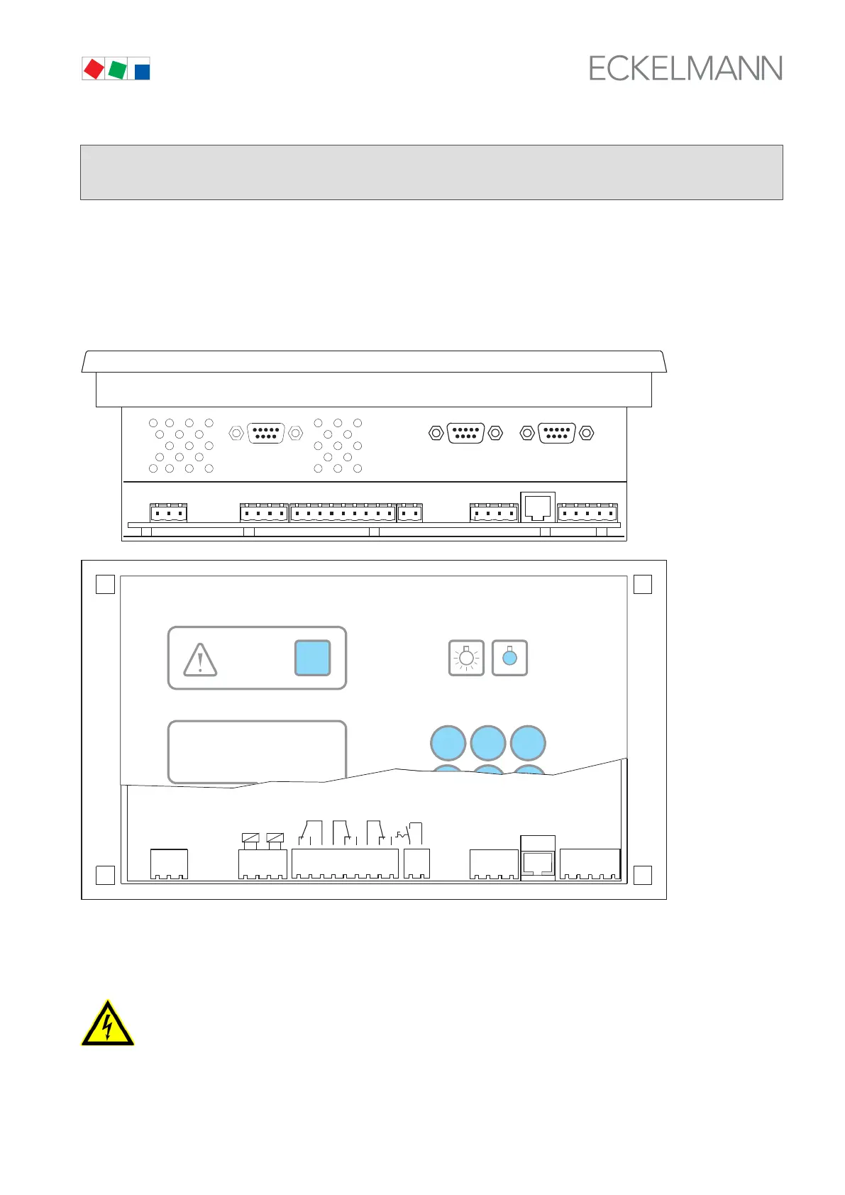
6.1 CI 3000 Store computer terminal diagram
A1
A2
B1
B2
RELAY OUTPUTS 230 V
16
18
15
25
28
26
35
38
36
PE
L
N
1
2
91
92
93
94
95
GROUND
9V
GROUND
24 V
SHIELD
1
2
3
4
SHIELD
GROUND
CAN-LOW
CAN-HIGH
INPUTS
230 V
POWER SUPPLY
230 V~ 50-60 Hz
MODEM
9-PIN
D-SUB CONNECTOR
(MALE)
COM 2
9-PIN
D-SUB CONNECTOR
(MALE)
ZNR. 35365 08 133 E3
AL.1AL.2
PRIO.1*PRIO.2*
LIGHT
789
RESET
PRIO 2
ALARM
PRIO 1
X
SIOX
SUPPLY
SIOX
OUT
CAN BUS
LIGHTING
*Relay status PRIO 2/1: Device switched on, no alarm
AUX
COM 3
(CI 3100 ONLY)
9-PIN
D-SUB CONNECTOR
(MALE)
SIOX OUT Data cable output
SHIELD Shield
SIOX SUPPLY Power supply for the SIOX module(s)
Warning - hazardous electrical voltage!
In order to guarantee reverse voltage protection,
only coded mating plugs are to be used on the assembly connections.
A detailed description of the connection and terminal configuration of the store computer and its components is
contained on the following pages.