Function of CI 3000
29
Version 2.09 09. April 2014
4.11.1 Totalizer and peak load monitoring
With the assistance of the totalizer (see picture in the following chapter), the values of a number of metering
points (e.g. meter for electricity, water, gas and heat) in menu 6-1-6-2 can be combined to generate a total
value. Generally, for each totalizer, one limit value monitoring with prioritised alarm/message is possible.
In addition, totalizers can also be assigned the functionality ”Watersave”. The purpose of this function is to moni
tor the water consumption and interrupt it if required.
Mode of operation: in the event of an overshoot of a parameterisable flow rate, i.e. total water consumption,
caused perhaps by a burst water pipe or a severe leak, a parameterisable SIOX output (menu 6-1-6-2) is
switched, activating a solenoid valve which interrupts the water supply. This function can be linked to the block
lock so that monitoring of the water consumption is only active during periods when the alarm system is primed
(e.g. at night when the store is closed).
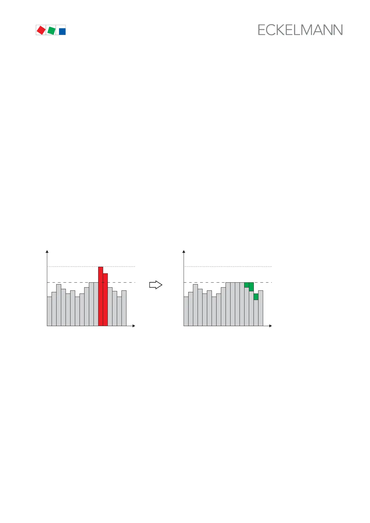
4.11.2 Load Shedding Manager (LSM)
The task of a load management system is to minimise the average recorded demand over a 15 minute period
(and thus also the demand charge), without compromising operating processes. The purpose of a load manage
ment system is to minimize the demand or capacity charge for electric power without negatively affecting opera
tions. Demand peaks should be kept as low as possible by temporary off-cycling or setting-back suitable electric
loads during peak demand periods and on-cycling or setting-up other loads during off-peak periods. Above all,
demand at any given time should not exceed the defined maximum capacity (contract capacity) for any length of
time or by any significant amount. Consumers are shutdown via SIOX relay outputs (menu 6-1-6-3-2).
without optimizing
500
350
kW
t
ZNR. 51203 68 330
500
350
kW
t
ZNR. 51203 68 330 D0
with optimizing
LSM acts as a peak demand monitor and its control limits are aligned to the current power demand measured
within a defined period. It compares the target and actual power level at fixed intervals (15 minutes, synchro
nized with the power company) and initiates load shedding if and when necessary.
Twenty load shedding stages are prioritized in ascending order. Stage 1 is shed first when load shedding be
comes necessary. Should this reduction of load be inadequate, the next stage (Stage 2 to 20) is shut down. This
continues until either power load drops to within the neutral zone or the highest load shedding stage is reached
(escalation strategy).
On first being started, LSM works in non-synchronized mode and initiates load shedding when maximum de
mand is exceeded. Energy and demand metering is not synchronized with that at the power company until the
next synchronizing signal is received from the power company.
Existing electric loads suitable for load shedding can be assigned at will to any load shedding stage. Using the
zero-potential relay outputs of its SIOX, the load shedding manager (LSM) can influence as many consumers as
required, using CAN bus messages it can influence the LDS components, and via DDC (Digital Direct Control)
the building control technology.
Optimum values can be defined for the Min. Time and Max. Time parameters of a load shedding stage and thus
imposed on Load Shedding Manager. It is appropriate to provide digital feedback also for individual electric
loads that are shed via SIOX Extension Module relay outputs.