Installation and Startup of CI 3000 / SIOX
34
Version 2.09 09. April 2014
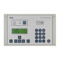
Insert the CI 3000 Store Computer with fitted rubber gasket (2) from the outside into the cutout in the control
panel (3) and fasten to the mounting frame behind (4) by four screws (6):
ZNR. 51203 68 030 D0
(6) M3 x ( 13 + d) mm
(2)
(3)
(4)
(1)
(5)
d
(1): Front panel
(2): Rubber gasket
(3): Control panel
(4) : Mounting frame
(5): Insert nut M3
(6): Fastening screws
See Section “Specifications” for electrical enclosure, measurements and panel mounting cut-out.
For wiring details see the chapter “Pin and Terminal Assignments”.
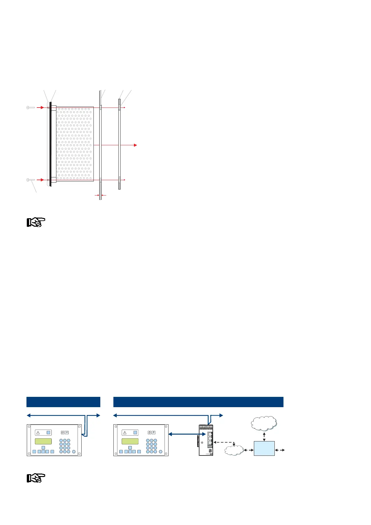
5.2 CAN bus
It is not necessary to set a CAN bus address as the store computer has been permanently allocated the address
111. For details on the connection to the CAN bus see chapter 6.1.4.
5.2.1 Fast CAN bus connection
If a plant is monitored remotely using the PC software LDSWin and the intention is e.g. to call up temperature
data cyclically via the network then this data can be accessed quicker via a fast CAN bus connection between
CI 3000 and Combi gateway.
Requirements:
- The use of a Combi Gateway
- The parameter CAN bus fast (menu item 6-1-1) must be set to yes and
following the store computer must be restartet by simultaneously pressing the MODE + ESC + 8 keys.
The following sketch illustrates the mode of operation:
Standard
MODEESC
PRIO 1
PRIO 2
,
9
WXYZ
7
PQRS
8
TUV
6
MNO
4
GHI
5
JKL
3
DEF
2
ABC
1
0
ALARM
RESET
>V5.0
ZNG: 102 430 E0
CAN2
RS232
Ethernet
USB
LED1
WDOG
LED2
24V
5V
CAN bus (
50 kbit - max. 500 m)
MODEESC
PRIO 1
PRIO 2
,
9
WXYZ
7
PQRS
8
TUV
6
MNO
4
GHI
5
JKL
3
DEF
2
ABC
1
0
ALARM
RESET
CAN bus (
50 kbit - max. 500 m)
CAN bus
(250 kbit
max. 100 m)
Fast
Internet
LAN
Router
(VPN)
Combi Gateway
Detailed information on the connection and mode of operation of the XML/LAN combi gateway is
provided in its operating instruction.