Function of CI 3000
31
Version 2.09 09. April 2014
the system operator and information gathered by the LDSWin software from the plant power demand
profile. Correct adjustment of setpoints, meaning efficiency and reliability of the load optimization
system, can readily be reviewed and checked from this recorded data.
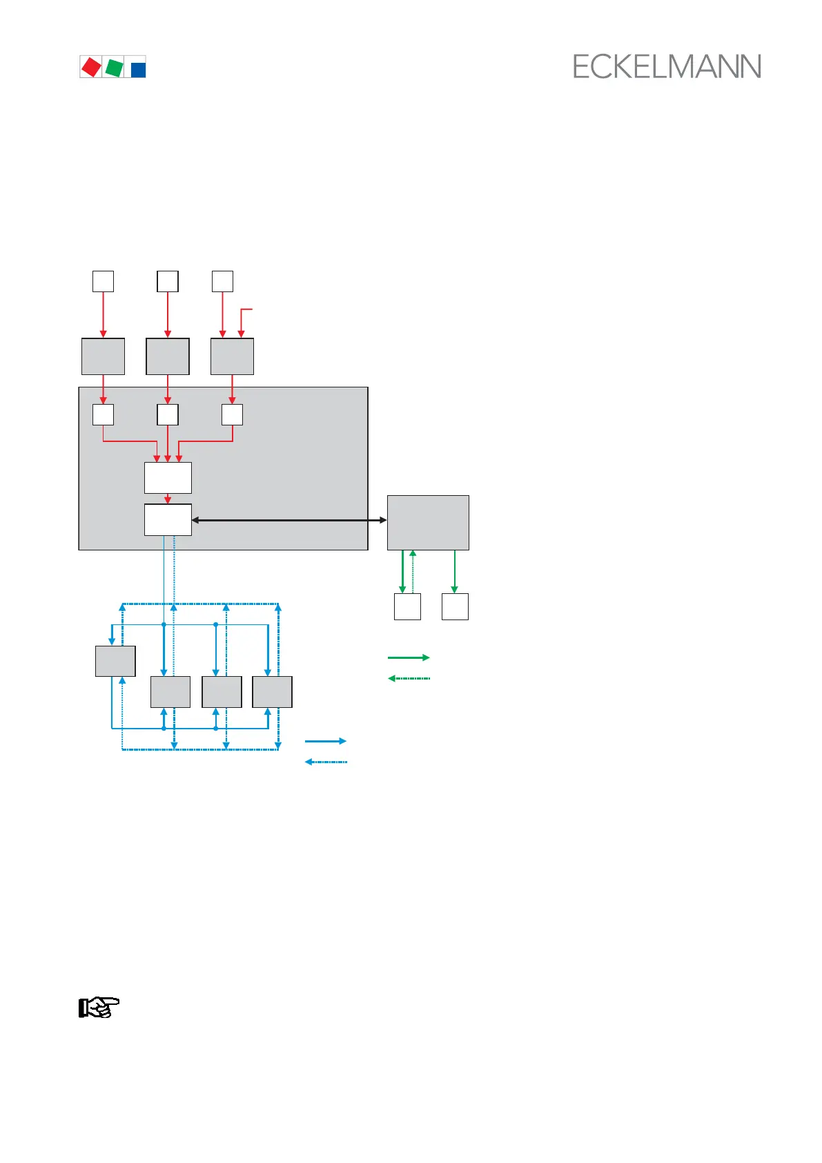
The following diagram outlines how load management acts on the various electric loads and how communica
tion takes place between LSM and the electric loads via the CAN bus:
UA 300
FAMILY
SIOX
DIGITAL IN-/
OUTPUT
ENERGY METER
ENERGY RECORD
TOTALIZER
CI 3000
OTHER CONSUMERS (E.G. BAKING OVEN, DISHWASHER)
DIGITAL SIGNALS
LOAD MANAGEMENT
BYTHE VS DELEGATED BY LSM
LOAD SHEDDING COMMAND BY CAN BUS
REQUEST/ FEEDBACK BY CAN BUS
LOAD SHEDDING COMMAND BY DIGITAL SIOX OUTPUT
FEEDBACK BY DIGITAL SIOX INPUT
VS 3000
UA 300
FAMILY
UA 300
FAMILY
CAN bus
LSM
SIOX SIOX SIOX
ZNR. 51203 68 230 E0
DIGITAL SIOX INPUTS
?
SYNCHRON IMPULSE FROM THE POWER COMPANY
4.12 M-bus Interface for consumption data capture
The M-bus (meter bus) is a field bus for the capture of e.g. gas, water or power consumption data.
It is transmitted serially from the connected meters (slaves / field devices) to a master (M-bus gateway) via a
reverse-polarity protected twin wire cable. The M bus gateway itself is connected to the store computer’s COM2
interface, the activation of the interface is carried out in menu 6-1-9.
For detailed information see chapter 5.8 “Connection of the M-bus Gateway”.