Installation and Startup of CI 3000 / SIOX
40
Version 2.09 09. April 2014
5.5.2 Configuring of SIOX
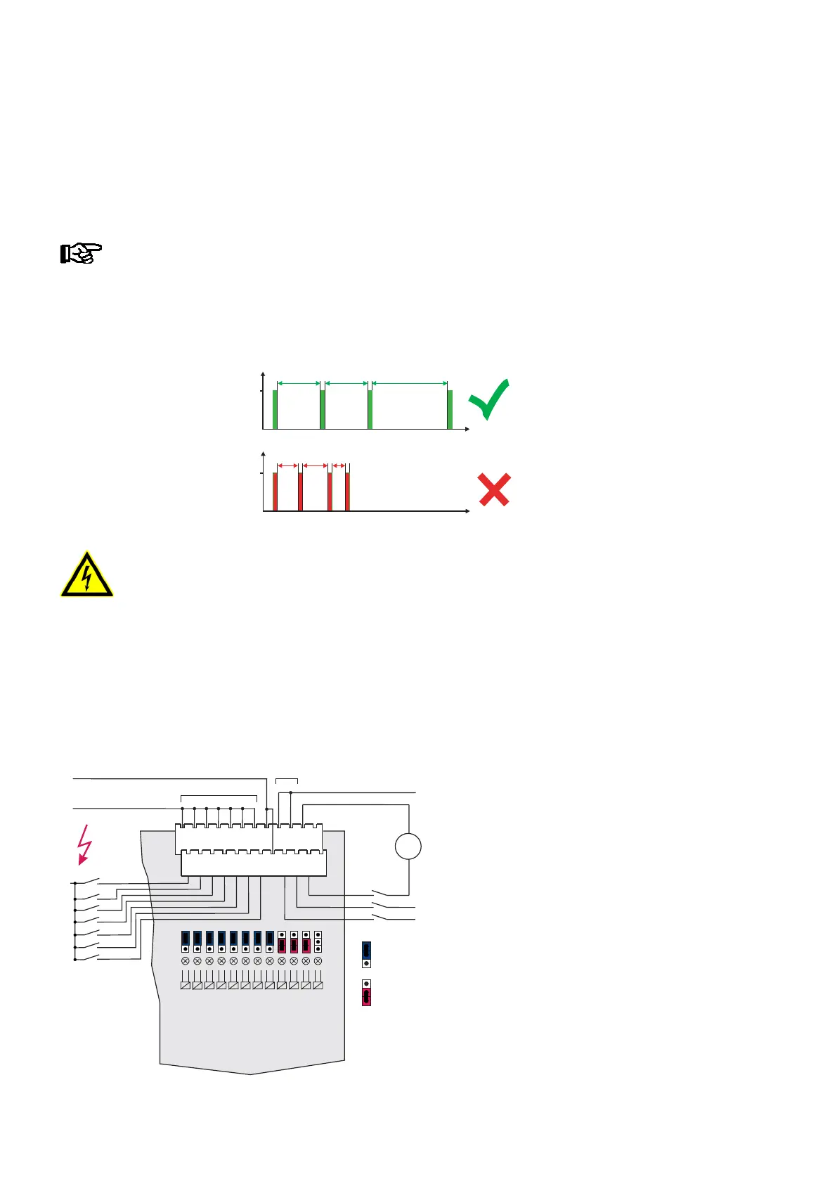
The 12 digital inputs (terminals A1, A2 / .. / L1, L2) of each SIOX Extension Module SIOX can be configured for
24/230 V AC using jumpers (see wiring examples in the picture).
The inputs only support alternating current signals!
Low-voltage DC signals, e.g. 24 V DC, are not recognized.
Exception: - 24 V DC meter pulses are detected (S0 interface, CI 3000/CI 3100 ONLY)!
Condition: 1. Minus 24 V DC MUST be supplied at the terminal level (A2 .. L2)!
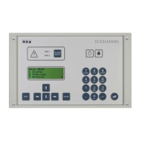
Condition: 2. S0 pulses must be spaced at intervals of minimum 50 ms for the to be counted!
Pulses timed at shorter intervals will not be detected!
ms
ZNR. 51203 80 330 DE
F0
> 50
S0
ms
S0
50 50
< 50 < 50 < 50
Warning - hazardous electrical voltage!
Danger of electric shock! Jumpers must always be configured while disconnected from power
and with connectors removed from inputs (terminals A1, A2 / .. / L1, L2), because these terminals
may carry 230 V AC power! The SIOX Extension Module will be destroyed if 230 V AC power is ap
plied to an input configured for 24 V AC!
Wiring of digital inputs:
230 V AC: The N conductors must be connected on one terminal level (A2 .. L2)!
24 V AC/DC: If 230 V AC and 24 V AC/DC inputs are required on a SIOX module
they must be seperated by one input which must be connected to PE!
Configuration:
230 V AC
For alarm and message signals
24 V AC
For alarm and message signals
CI 3000/CI 3100 Store Computer ONLY:
To register meter pulses
(S0 interface)
230 V AC
2
1
11
9
12
ZNR. 51203 67 631E2
4
3
6
5
8
7
10
230 V AC
24 V AC
N
L1
A2
B2
C2
D2
E2
F2
G2
H2
I2
J2
K2
L2
A1
B1
C1
D1
E1
F1
G1
H1
I1
J1
K1
L1
- (S0-Minus)
+ (S0-Plus)
~
+ (S0-Plus)
24 V AC
24 V DC
PE
ALARM/METER INPUT
SIOX MODULE