Chapter 3
| Network Settings
Ethernet Settings
– 47 –
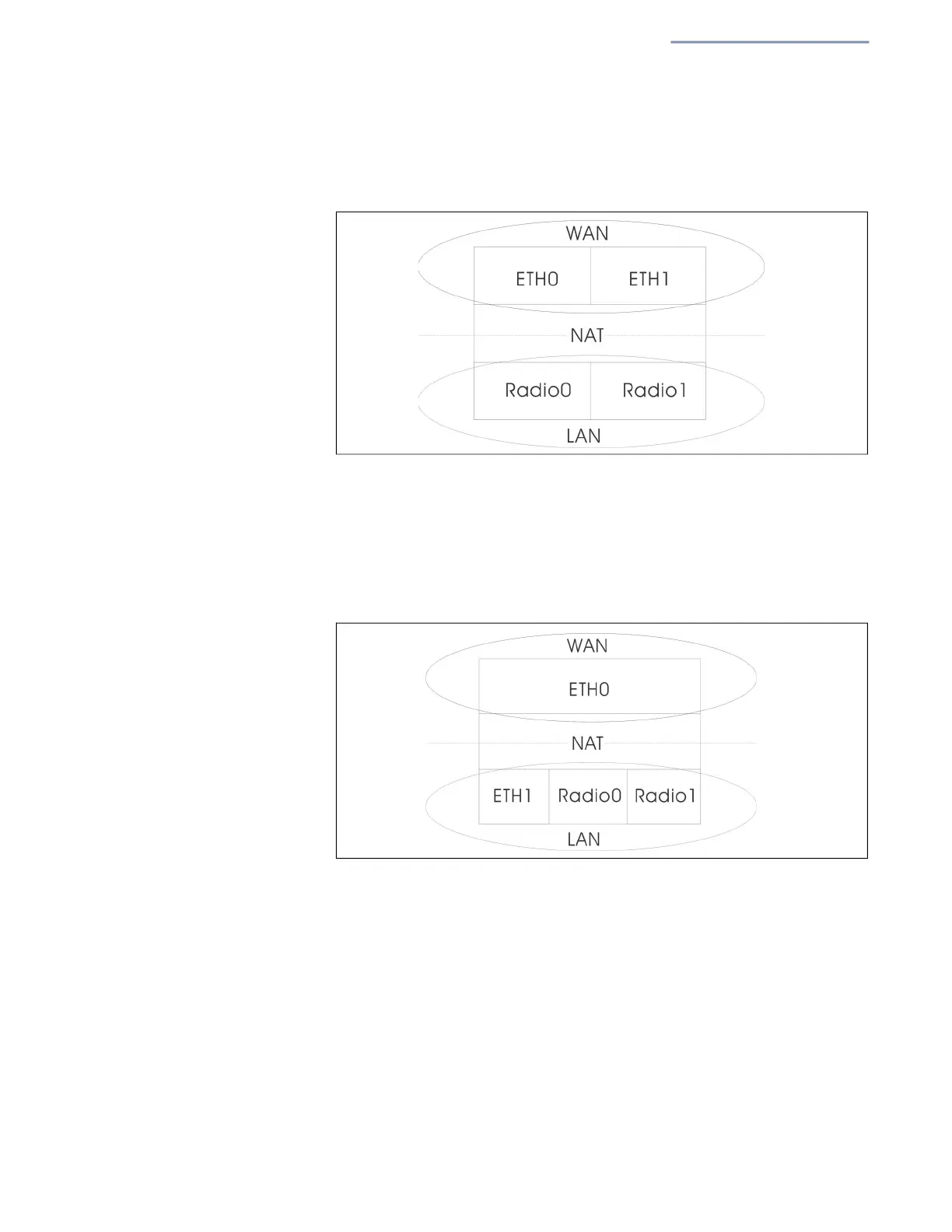
In the following figure, Ethernet Port 0 and Ethernet Port 1 are both
attached to the WAN.
Figure 29: Bridge to Internet
Route to Internet — Configures an interface to be a member of the LAN.
Traffic from this interface is routed across the access point and out through
an interface which is bridged directly to the Internet. By default, Ethernet
Port 1 is routed to Internet, allowing management access via a direct
connection to a PC configured with
an address in the same subnet.
F
igure 30: Route to Internet
Network Name — The network to be routed. The default is “Default
local network” as displayed under LAN Settings – Local Networks.
Add to Guest Network — This port can only support the guest network.
Hotspot Controlled — This port can only access hotspot services. Click
the link to open the Hotspot Settings page. See “Hotspot Settings” on
page 52.
VLAN Tag Traffic — This port transmits tagged traffic from a specified
VLAN. Select the VLAN ID from the configured list, or click the link to open
the Wireless VLAN Settings page and create a VLAN ID. See “VLAN
Settings” on page 78.