60 DCM00044 REV. 14
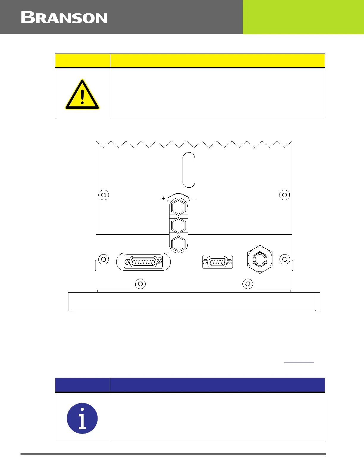
To DECREASE cooling air flow rate, turn the cooling air control knob clockwise.
Figure 6.1 Speed Controls and Cooling Knob Location
6.2.5 Down Stop Adjustment
The down stop is used as a safety mechanism to prevent contact between the Horn and
Anvil if the welder is cycled without the part(s) to be welded. Unless otherwise specified, a
0.004” (0.10 mm) gap between the Horn and Anvil is recommended. See Figure 6.2
for
the Down Stop location.
CAUTION General Warning
Compressed airflow should be directed away from the operator at all
times.
INCREASE
SPEED UP
SPEED DOW N
CO O LING
SIGNAL
ENCODER
DECREASE
50
NOTICE
Some applications require no down stop due to thickness of the
material.
 Loading...