14 DCM00003 REV. 07
Subsequently, because of the increased Power less time is required deliver the same
amount of Energy. This relationship is illustrated in the power diagram (Figure 2.7):
Figure 2.7 Power, Time, and Energy relationship
Resonant Frequency
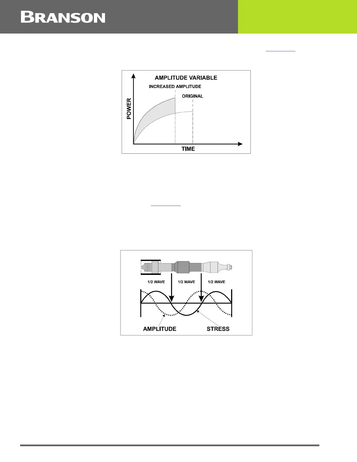
The ultrasonic tooling acts as a spring having node points and anti-node points. The
mechanical energy used to vibrate the tool is created by the converter. As the vibrations
are propagated through the acoustical tool, a harmonic resonance is established
consisting of nodes and anti-nodes. This action results in a resonant wave being
transferred through the tooling (Figure 2.8
). The efficiency of the resonant wave transfer
depends on the natural resonant frequency of the horn and is determined by two factors:
• The speed of sound through the material
• The geometric shape of the object
Figure 2.8 Resonant Frequency
Avoiding An Overload Condition: It is possible to increase the Amplitude and or the
Pressure to a point where the power available is not adequate to initiate or maintain
vibration under the given mechanical load. At this point, the power supply will stall
resulting in an Overload condition. Electronic circuits in the system will protect the power
supply if this condition exists.
Welding To Time: In specific applications, ‘Welding To Time’ may be desired. As previously
mentioned, there are three primary variables that interact; they are:
• TIME: The duration of applied ultrasonic vibration
• AMPLITUDE: The longitudinal displacement of the vibration
• FORCE: The compressive force applied perpendicular (normal) to the direction of vibration