16 DCM00002 REV. 16
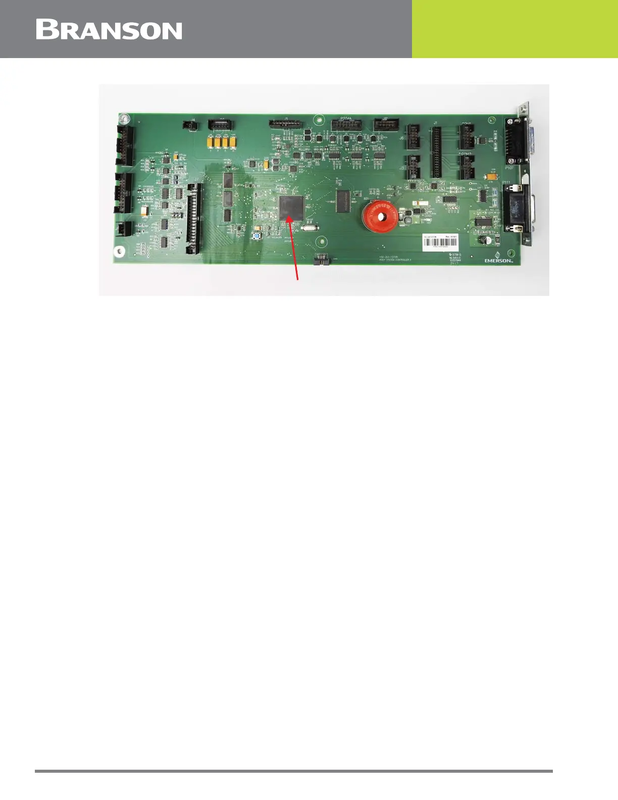
Figure 2.2 The CPU Board
Front Touchscreen Panel and Bezel Assembly
It is held by four upper screws which are accessible from inside the enclosure and four
lower screws which are accessible from outside the enclosure through the ventilation slots
in the bezel. Removal of the front bezel allows access to the following components which
are housed inside it:
• Touchpanel: The sensing element which provides the user interface with the controller
• LCD Screen: The visual display through which instructions are communicated to the user. It is
mounted directly behind the touchpanel
• Display Board: Contains the video control circuits for the LCD Screen. This board is mounted
directly behind the LCD controller
• Front Panel Board: Houses the alarm beeper and the four diagnostic lights which are located to
the right of the touchscreen on the front bezel
• Power Switch: Used to turn the Controller on and off
Motor Control Board
Contains the control circuit for controlling actuators which are equipped with a stepper
motor driven gather mechanism.
Pneumatic Kit
Refer to the Special Information Instruction Set.
U1
 Loading...