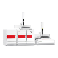
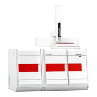
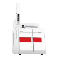
multi N/C 2100S Transport and storage
107
CAUTION
Always connect the system components to the multi N/C 2100S when it is switched off!
Before connecting the mains cable ensure that the main switch on the back of the
equipment is set to "0"!
Only use the IEC connection cable included in the scope of delivery for the connection to
the mains supply (VDE label, 1.5 m long). Extensions of the
supply cable are not
NOTICE
Settled condensation and temperature differences can damage individual components
of the analyzer during recommissioning.
Allow the analyzer multi N/C 2100S to acclimatize for at least one hour before
commissioni
ng after positioning it in the operating room.
Make the mains connection as follows:
1. Connect the low-heat connection cable to the mains connection at the rear of the
analyzer (4 in Fig. 35 p. 106).
2. Connect the mains plug of the low-heat connection cable to a grounded socket.
NOTICE
The operator is responsible for providing the necessary gas
connection. Make sure that
the preliminary pressure at the pressure reducer is set to between 4 and 6 bar.
Make the carrier gas connection as follows:
1. Connect the connection hose supplied to the pressure reducer of the gas supply and
the gas connection "O
2
/Air" on the equipment backplate (9 in Fig. 35 p. 106).
2. Connect the connection hose supplied to the pressure reducer of the gas supply and
the gas connection "aux gas" on the equipment backplate (10 in Fig. 35 p. 106).
3. Set the preliminary pressure at the pressure reducer to between 4 and 6 bar.
The connections for carrier gas and auxiliary gas on the device are quick-release
connections:
The hose is inserted into the connection and thereby attached.
To undo the hose the red ring must be pressed back and the hose pulled off the
connection.
Connect the mains cable
Connecting the gas supply
 Loading...
