Transport and storage multi N/C 2100S
106
8. Fill the combustion tube and install the combustion tube in the combustion furnace
(see sections "Filling the combustion tube" p. 75 and "Inserting the combustion tube"
p. 76).
9. Install the TIC condensate container and condensation coil (see section "Installing the
TIC condensate container and condensation coil" p. 81).
10. Place the reagent bottle with the drip tray into the analyzer.
11. Close the doors of the analyzer.
12. Position any add-on devices at the intended location and connect them. Observe in
this regard the user manuals of the add-on devices.
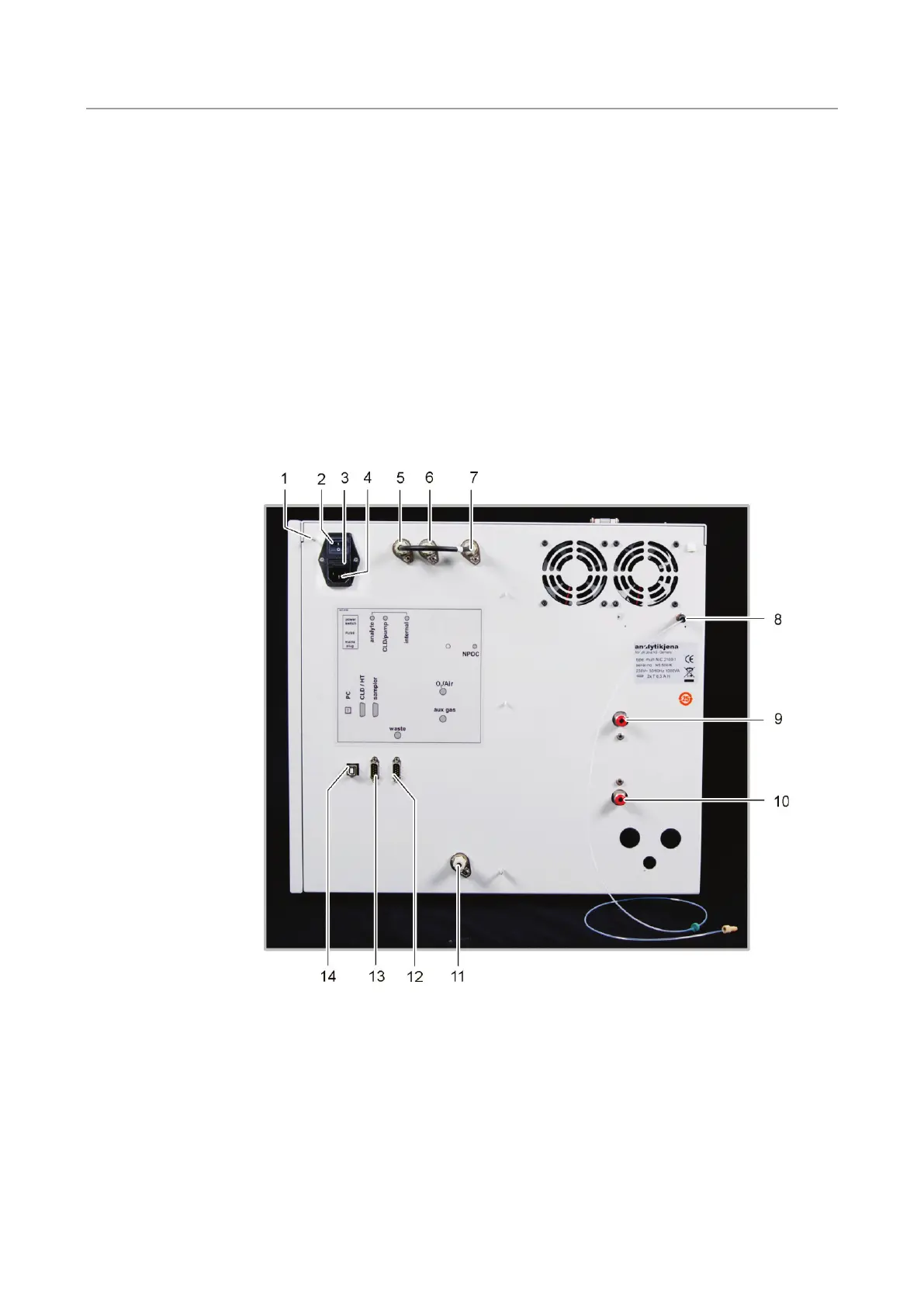
9.3.2 Connecting the analyzer
The mains connection and media connections are on the analyzer backplate:
1 Connection of the neutral conductor at the sampler
2
Main switch to switch the analyzer on and off
Holder for mains fuse
Mains connection
Gas connection "analyte" (connected to gas
connection "internal" via a hose bridge)
Gas connection "CLD/pump!
Gas connection "internal"
Connection NPOC purging gas "NPOC"
9 Carrier gas connection "O
2
Connection for auxiliary gas for pneumatically
connected locks "aux gas"
Waste "waste"
RS 232 interface for the sampler "sampler"
RS 232 interface for CLD and HT module "CLD/HT"
14
USB port for PC "PC"
Fig. 35 Mains connection and gas connections at the multi N/C 2100S

 Loading...