Function and setup multi N/C 2100S
28
3.1.6 Indicator and control elements, connectors
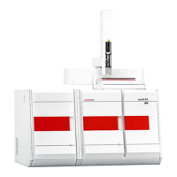
The green LED at the left door of the analyzer illuminates after the device has been
switched on.
Fig. 15 LED to indicate readiness for operation
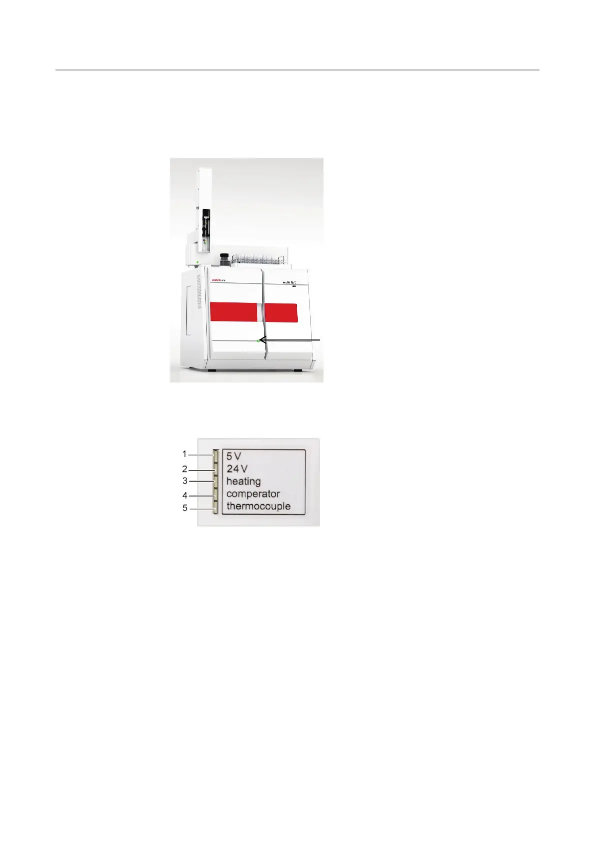
The LED strip behind the right door indicates different operating states of the analyzer.
1 internal firmware controller
2 device voltage
3 furnace heating
4 furnace comparator (illuminates with excessive
temperature)
5 thermocouple (illuminates with faulty
thermocouple)
Fig. 16 LED strip (right door open)
Main switch, mains connection, equipment fuse, media connections (gases and waste)
and the interfaces for connecting the PC and the accessories are at the back of the
multi NC 2100S.
A diagram at the center of the backplate explains the different connections.
LED displays
Main switch, interfaces,
gas connections at the
back of the equipment

 Loading...