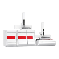
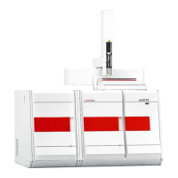
multi N/C 2100S Maintenance and care
65
7.2 Adjustment and setup tasks
7.2.1 Adjust autosampler
An adjustment of the sampler is necessary:
before the first start
after every syringe replacement
after every manipulation at the locks (e.g. catalyst replacement and maintenance
tasks)
during recommissioning after transport or storage
During the adjustment the cannula must be adjusted relative to position 1 on the
sample tray, the combustion furnace and the TIC reactor.
Adjust the sampler in the following order:
1. at position 1 of the sample tray
2. at the combustion furnace
3. at the TIC reactor (not for multi N/C 2100S pharma)
Check and adjust always all three positions!
x and y direction
Adjust the positions as precisely as possible in the x and y directions! The cannula must
immerse into the sample cup at the center of position 1.
The following are guide values:
Position 1 Furnace TIC
x direction 5 90 1010
y direction 1435 475 80
z direction (immersion depth)
Select the immersion depth of the cannula (z direction) in the TIC reactor (septum-
free lock) as just sufficient to achieve system tightness. You can check the system
tightness in the window S
YSTEM STATE (MFC1 and MFM1 show the same value if the
system is tight, Target: 160 ml/min).
For the septum lock select the immersion depth of the cannula (z direction) in the
TIC reactor such that approx. 3 mm of the cannula is still visible above the lock.
When adjusting the cannula in the z direction in the sample cups (position 1) take
into account the use/non-use of stirring rods.
Carry out the adjustment as follows:
1. Enter the syringe size:
• With the menu command C
ONFIGURATION EDIT OPTIONS open the window
O
PTIONS tab ANALYZER COMPONENTS.
• In the group S
YRINGE in the list SIZE select the specified syringe volume.
Adjust position 1/TIC
reactor position/furnace
position
Recommendations for the
coordinates to be set

 Loading...