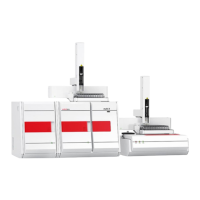
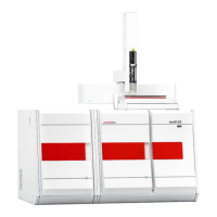
Connecting add-on devices multi N/C 2100S
46
Protection 2 x T4.0 A H
Typical average power consumption 200 VA
PC interface RS 232
Interference suppression (electromagnetic
compatibility)
in accordance with the rules of
EN 55011 Group 1, Class B interference-
protected (according to EN 61326-1 suitable
for use in basic electromagnetic
environments)
3
) produced from dry carrier gas in the ozone generator is destroyed in
the downstream ozone destroyer if the analyzer is used as intended. Furthermore, the
potential concentrations are harmless. Various safety measures cause the automatic
shutdown of the o
zone generator.
If a smell of ozone occurs in the CLD, switch off the device immediately and contact the
Service of Analytik Jena AG.
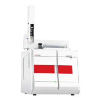
Connect the chemiluminescence detector to the analyzer as follows:
1. Place the chemiluminescence detector to the right of the analyzer.
Connect the carrier gas to the connection with quick-release coupling 8 in Fig. 20 p. 45).
2. Establish the gas connection between CLD and multi N/C 2100S:
• CLD connection 9 in Fig. 20
• Analyzer connection 6 in Fig. 17 p.29.
3. Connect the corresponding serial interface "CLD/HT" on the equipment backplate of
the analyzer (13 in Fig. 17) via the serial data cable supplied to the RS 232 interface
of the chemiluminescence detector (5 in Fig. 20).
4. Switch on the CLD.
The lamp on the front panel of the CLD indicates readiness for operation.
5. Check the configuration via the menu command I
NSTRUMENT SYSTEM INFORMATION in
the window
SET-UP INFO. If necessary, modify the configuration:
• Exit the program multiWin.
• On the Windows user interface start under START PROGRAM FILES MULTIWIN
MULTI
WIN SET-UP TOOL the SET-UP TOOL.
• In the DETECTOR list select the option CLD.
• Exit the SET-UP TOOL with [CREATE].
• Change the configuration in the window
MULTIWIN SET-UP TOOL.
Installation at the
analyzer
 Loading...
