Contents multi N/C 2100S
6
Figures
Fig. 1 Front view (doors open) .................................................................................... 17
Fig. 2 Lateral view left (side wall removed) ................................................................ 18
Fig. 3 Locks at the top of the device ............................................................................ 18
Fig. 4 Toggle switch for the manual operation of the septum-free TC lock .............. 19
Fig. 5 Hose diagram ..................................................................................................... 20
Fig. 6 Needle valve to adjust the NPOC purging flow (see arrow) ............................. 21
Fig. 7 Condensate pump .............................................................................................. 22
Fig. 8 Phosphoric acid pump ........................................................................................ 22
Fig. 9 Different Fast connector designs ....................................................................... 23
Fig. 10 Fingertight screw connection ........................................................................ 23
Fig. 11 Combustion furnace (see arrow) ................................................................... 24
Fig. 12 Condensation coil and TIC condensation module ......................................... 25
Fig. 13 Water traps ..................................................................................................... 25
Fig. 14 Halogen trap ................................................................................................... 26
Fig. 15 LED to indicate readiness for operation ........................................................ 28
Fig. 16 LED strip (right door open) ............................................................................ 28
Fig. 17 Connections on the rear of the device ........................................................... 29
Fig. 18 Principle of operation..................................................................................... 31
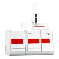
Fig. 19 AS 60 mounted on the analyzer multi N/C 2100S ....................................... 43
Fig. 20 CLD – display elements, mains connection and media connections ............ 45
Fig. 21 Media connections on the backplate of the solids module .......................... 47
Fig. 22 Window CALIBRATION - DATA OF NEW CALIBRATION ............................................ 51
Fig. 23 Window CURRENT SAMPLE DATA (with sampler operation) ............................. 53
Fig. 24 Window CALIBRATION - DATA OF NEW CALIBRATION ............................................ 54
Fig. 25 Disabling individual measured values of a calibration ................................. 55
Fig. 26 Window Link to Method ................................................................................ 57
Fig. 27 Window LINK WITH METHOD with three areas ................................................. 58
Fig. 28 Window SELECTION CALIBRATION report ............................................................ 59
Fig. 29 Adjusting the syringe piston .......................................................................... 67
Fig. 30 Water traps at the gasbox, left side panel opened ....................................... 71
Fig. 31 Halogen trap ................................................................................................... 72
Fig. 32 Angled FAST connector with connected hose ............................................... 89
Fig. 33 Replacing the Fingertight connection ........................................................... 89
Fig. 34 TIC sluice with septum seal ............................................................................ 90
Fig. 35 Mains connection and gas connections at the multi N/C 2100S............... 106

 Loading...