Proline Promag 53 MODBUS RS485 Troubleshooting
Endress+Hauser 109
A0008241
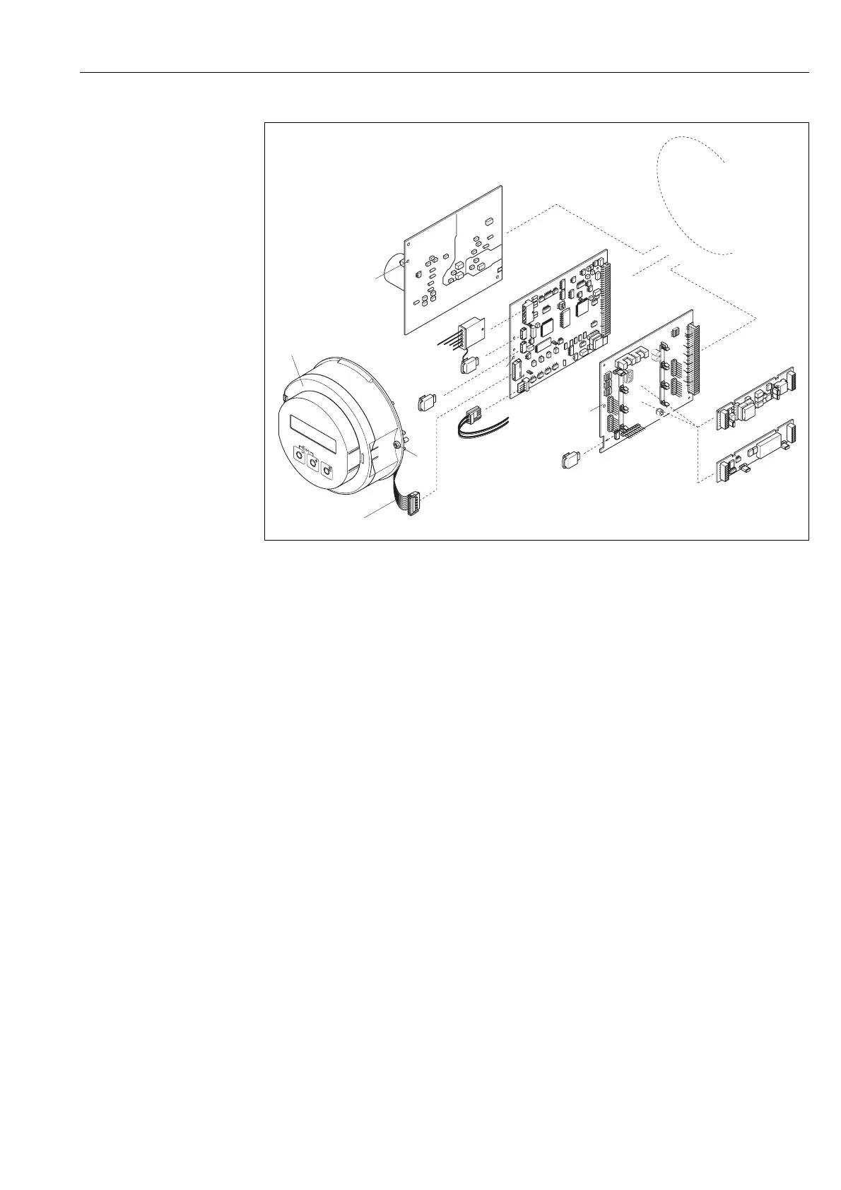
Fig. 61: Field housing: removing and installing printed circuit boards
1 Local display
1.1 Screws of electronics compartment cover
1.2 Ribbon cable (display module)
2 Aperture for installing/removing boards
3 Power unit board
4 Amplifier board
4.1 Electrode signal cable (sensor)
4.2 Coil current cable (sensor)
4.3 S-DAT (sensor data memory)
4.4 T-DAT (transmitter data memory)
5 I/O board (flexible assignment)
5.1 F-CHIP (function chip for optional software)
5.2 Pluggable sub-modules (current, pulse/frequency and relay output)
3
4
5
2
2
2
4.1
4.3
4.4
4.2
5.1
INPUT/OUTPUT 4
INPUT/OUTPUT 3
1
2
3
4
W
E
N
O
1
2
3
4
W
E
N
O
1
2
3
4
W
E
N
O
1
2
3
4
W
E
N
O
5.2
1.1
1
1.2
 Loading...


