Multi-Function Control ETMFC610 http://www.entecene.co.kr
CURRENT INPUT
Phase A
CURRENT INPUT
Ground
≥
Phase Pickup Set
≥
Phase Pickup Set
CURRENT INPUT
Phase B
≥
Phase Pickup Set
CURRENT INPUT
Phase C
≥
Neg Seq
'
Pickup Set
≥
Ground Pickup Set
Dropout delay
Temporary FI Time
FLTPA
Dropout delay
Temporary FI Time
Dropout delay
Temporary FI Time
Dropout delay
Temporary FI Time
Dropout delay
Temporary FI Time
Phase Fault Direction
=
Phase Direction Set
(None, For. or Rev.)
FLTPB
FLTPC
NEQ Fault Direction
= NEQ Direction Set
(None, For. or Rev.)
FLTPQ
Ground Fault Direction
= Ground Direction Set
(None, For. or Rev.)
FLTPG
CURRENT INPUT
SEF
≥
SEF Pickup Set
Dropout delay
Temporary FI Time
SEF Fault Direction
= SEF Direction Set
(None, For. or Rev.)
FLTPS
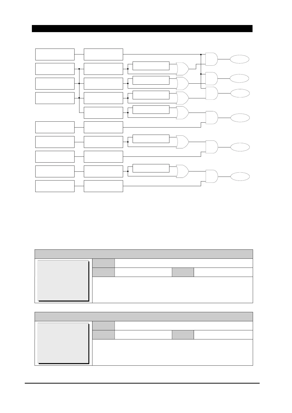
Figure 8-1. Fault Pickup Logic Diagram
8.1.3. FI Setting Time
This menu sets the delay times for fault indication(FI) detection.
GROUP # / FAULT INDICTION / FI SETTING TIME / Permanent
Range
1~180 sec
Default
20 sec
Step
1
Set delay time for Permanent Fault Detection. In case FI Type is ‘IV’
Type, this setting is applied.
GROUP # / FAULT INDICTION / FI SETTING TIME / Temporary
Range
1~180 sec
Default
2 sec
Step
1
Set delay time for Temporary Fault Detection. In case FI Type is ‘IV’
Type, this setting is applied.
>Permanent: 20
Temporary: 2
Type I delay: 0.03
[1~180:1sec]
>Permanent: 20
>Temporary: 2
Type I delay: 0.03
[1~180:1sec]