Multi-Function Control ETMFC610 http://www.entecene.co.kr
8.3.4. Negative Sequence Directional Controls (67Q)
Negative Sequence voltage V
2
provides negative sequence pole direction in power system.
Negative sequence direction is determined by comparing negative sequence voltage(V
2
) and
negative current(I
2
). If an angle from negative sequence voltage (V
2
) to negative sequence current
(I
2
) is within
90˚ based on Maximum Torque Angle, it is forward direction, otherwise, reverse
direction. Maximum Torque Angle is between ∠0˚ and ∠359˚. Maximum Torque Angle initial set
value leads from negative sequence voltage(V2) for ∠135˚.
If polarizing voltage drops minimum polarizing voltage, negative sequence direction control is
cancelled and negative sequence fault(fault indication type) and negative sequence
overcurrent(protection type) are not detected. On the other hand, if negative sequence direction
control type is set for ‘NONE’, fault and over current are detected regardless of direction.
Set negative sequence direction control type to detect negative sequence fault and overcurrent.
Depending on control type, negative sequence fault and overcurrent are detected in forward or
reverse or both direction.
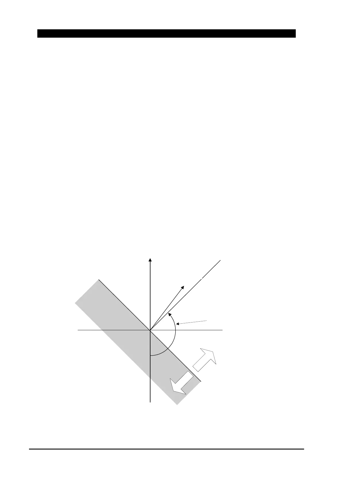
Following figure shows phasor graph of negative sequence current(I
2
) direction polarity.
Figure 8-46. Phasor Diagram for I
2
Directional Polarization
Ma
x
imum
T
o
rque Line
-V2
Zer
o
T
o
r
que
Lin
e
Fo
r
ward
R
everse
I2
Maximum Torque Angle :
set 135 degree
V2
Polarizing Referance
Voltage:
Fault Current