Multi-Function Control ETMFC610 http://www.entecene.co.kr
6.1.4. Fault Indication Section
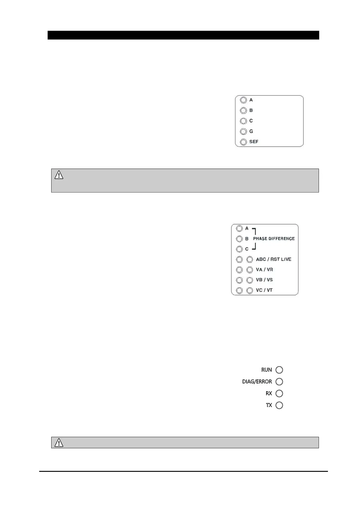
On fault detection, protection elements and phase are displayed which detects more than pickup
level or fault trip.
FAULT INDICATION
A, B, C : Indicates a phase fault has occurred on one of
the phase lines
G (GROUND) : Indicates an ground fault has occurred
SEF : Indicates a sensitive earth fault has occurred on
the neutral line
Figure 6-7. Fault Indication Section
NOTE :
Fault Indication LEDs will remain on after lighting, and will be turned off by "FI
RESET" command.
6.1.5. Voltage Element Section
Indicates that voltage element is occurred.
PHASE DIFFERENCE : Shows a Phase Difference
state between source side and load side voltage.
ABC/RST LIVE : Show Live Line status of source
side and load side
VA/VR, VB/VR and VC/VT : Shows Open Phase
Status on each phase.
Figure 6-8. Voltage Elements Section
6.1.6. System Diagnostic Section
Indicates Diagnostic status of ETMFC610.
RUN : Status of ETMFC610 systems shows normal
DIAG/ERROR : Status of ETMFC610 systems
shows warning
RX : Shows the data receiving status for remote
communication.
TX : Shows the data transferring status for remote
communication.
Figure 6-9. System Diagnostic Section
NOTE :
RUN LED is blinking when system functional status is normal
 Loading...