Multi-Function Control ETMFC610 http://www.entecene.co.kr
Phase direction control type can be set in order to detect phase fault and phase overcurrent.
Depending on control type, phase fault and phase overcurrent can be detected in Forward direction
or reverse direction or regardless of direction.
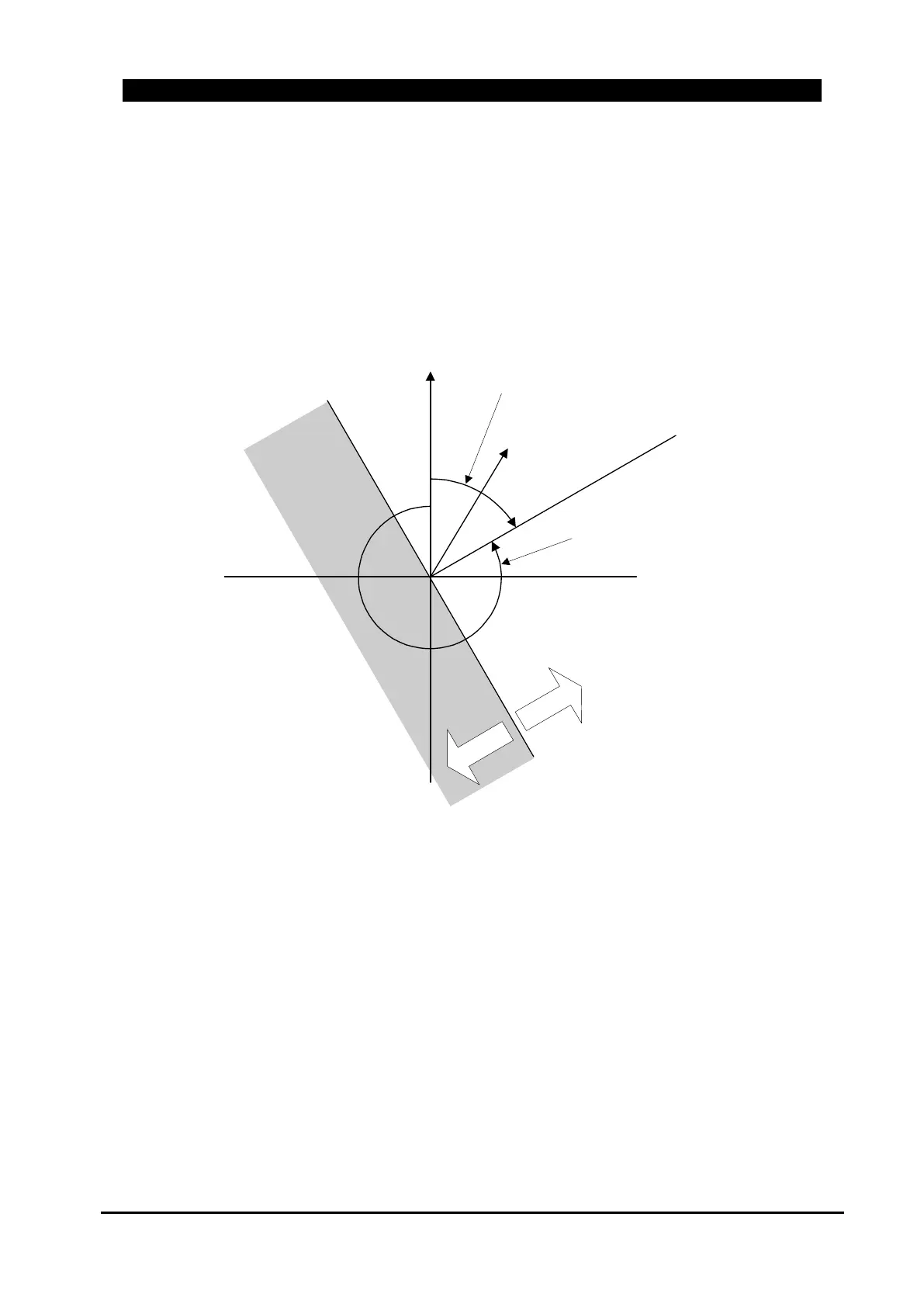
Following “Figure 8-44. Phasor Diagram for I
1
Directional Polarization” shows normal current
(I
1
) direction polarity phasor diagram in complex plane.
Figure 8-44. Phasor Diagram for I
1
Directional Polarization
Maxi
m
um
Torque
Li
n
e
V1
Ze
ro
T
o
rqu
e
L
i
n
e
For
w
a
rd
Reverse
I1
Maximum Torque Angle :
set 300 degree
Typical Fault Angle
Voltage: