Multi-Function Control ETMFC610 http://www.entecene.co.kr
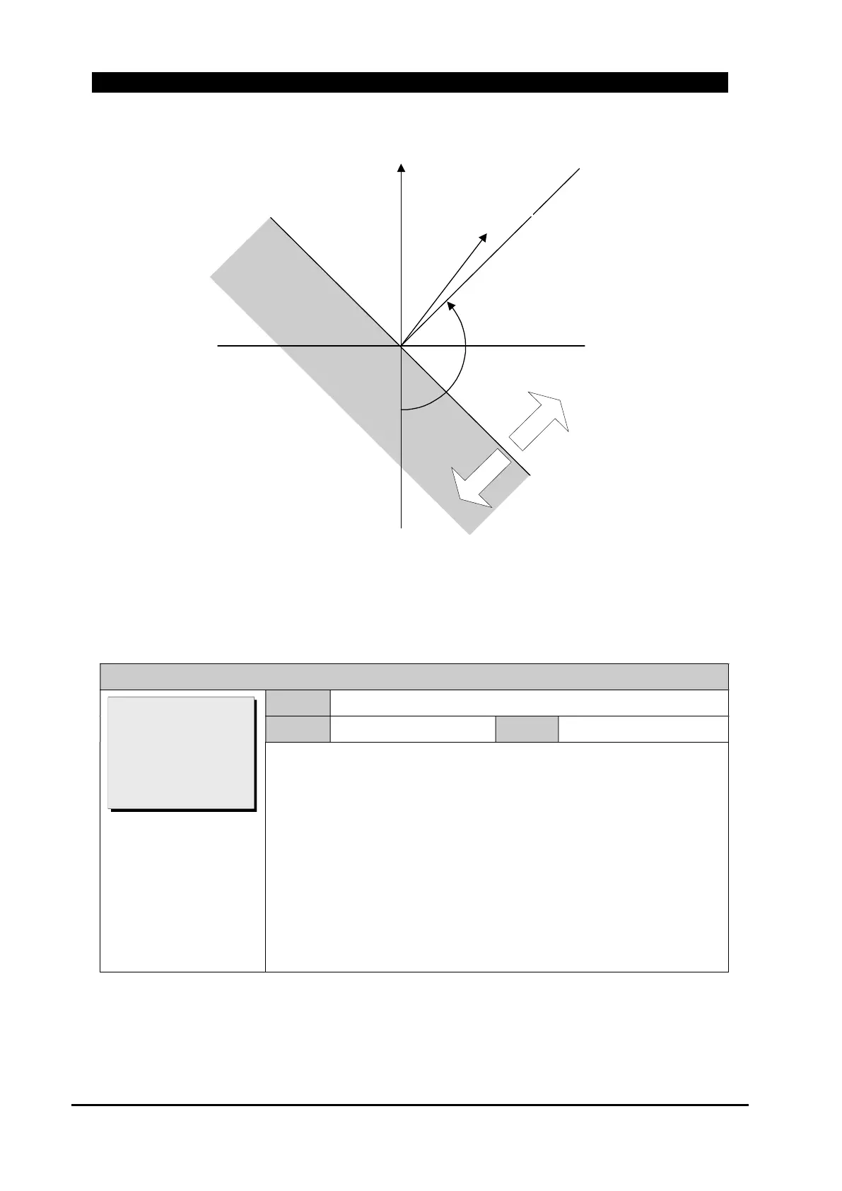
Figure 8-45. Phasor Graph for I
g
Directional Polarization
The ground direction control in following four settings should be enabled.
GROUP # / DIRECTION / GROUND / Type
Range
NONE, FORWARD, REVERSE
Default
NONE
Step
~
Set ground direction type.
NONE : Regardless of ground direction, ground fault and overcurrent
are detected by normal phase current(I
n
).
FOR : Ground fault and (+) Ground overcurrent are detected when
forward ground direction.
(-) Ground overcurrent is detected when reverse ground direction.
REV : Ground fault and (+) Ground overcurrent are detected when
reverse ground direction.
(-) Ground overcurrent is detected when forward ground direction.
M
ax
i
mu
m
Torq
ue L
ine
-V0
Zero To
rq
ue Line
Fo
r
ward
Rev
erse
Ig
V0
Polarizing Referance
Voltage:
Fault Current
>Type: NONE
M.T.A: 135
M.P.V(3V0): 0.30
Block OC: YES
[NONE/FOR/REV]
 Loading...