Multi-Function Control ETMFC610 http://www.entecene.co.kr
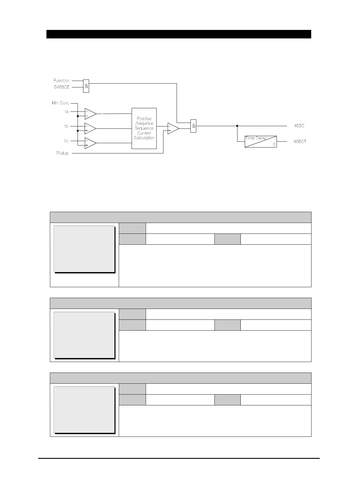
The figure below shows the function logic diagram of Broken Conductor.
Figure 8-49. Brocken Conductor(46BC) Function Logic Diagram
The Broken Conductor element in following settings should be enabled.
GROUP # / MONITORING / BROKEN CONDUCT / Function
Range
DISABLE, ENABLE
Default
DISABLE
Step
Set the function of broken conduct element as enable or disable.
If function = DISABLE, the feature is not operational.
If function = ENABLE, the feature is operational. When the feature
asserts an alarm condition, the device gives the alarm.
GROUP # / MONITORING / BROKEN CONDUCT / Pickup(I2/I1)
Range
1~100 %
Default
5
Step
1 %
Set the Broken Conductor pickup level.
GROUP # / MONITORING / BROKEN CONDUCT / Time Delay
Range
0.00~600.00 sec
Default
4.00
Step
0.01 sec
Set the Broken Conductor function delay time.
>Function: DISABLE
Pickup(I2/I1): 5
Time Delay: 4.00
Max.I: 500
[DISABLE/ENABLE]
Function: DISABLE
>Pickup(I2/I1): 5
Time Delay: 4.00
>Max.I: 500
[1~100:1 %]
Function: DISABLE
Pickup(I2/I1): 5
>Time Delay: 4.00
>Max.I: 500
[0.00:600.00:0.01 s]
 Loading...