Multi-Function Control ETMFC610 http://www.entecene.co.kr
3) ETHERNET PORT
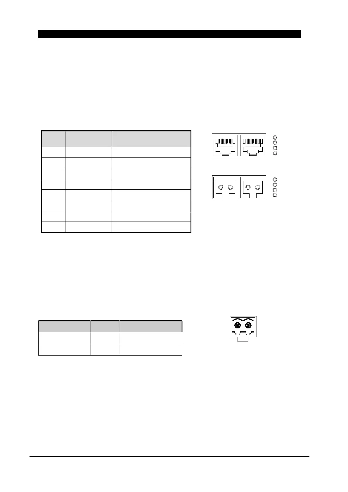
Ethernet1 and 2 are RJ-45 that has 8pins as in ‘Table 5-4.Ehternet(TP) Pin Description’.
Ethernet port can be selected between TP and FX type. If FX type is used, LC type optical
communication will be supported.
Ethernet 1 and 2 are composed of duplex switch ports
Table 5-4.Ethernet(TP) Pin Description
Pin
Wire Color
10Base-T Signal
100Base-TX Signal
1 White/Green Transmit+
2 Green Transmit-
3 White/Orange Receive+
4 Blue Unused
5 White/Blue Unused
6 Orange Receive-
7 White/Brown Unused
8 Brown Unused
4) IRIG-B Connector - Option
It is a IRIG-B connector for time synchronization function using Time Synchronization module.
Input current : 4 mA at 5 V (typical)
Table 5-5. IRIG-B Pin Description
Figure 5-5. IRIG-B
Connector Pin
Description
IRIG-B
Connector
1 POSITIVE
2 NEGATIVE
2 1
- +
[ Ethernet TP ]
[ Ethernet FX ]
Figure 5-4.Ethernet Port
Eth2 Eth1
1L/ACT
1SPEED
2L/ACT
2SPEED
1L/ACT
1SPEED
2L/ACT
2SPEED
Eth2 Eth1