RECLOSER CONTROL EVRC2A-N6,NT http://www.entecene.co.kr
165
ENHANCED
TECHNOLOGY
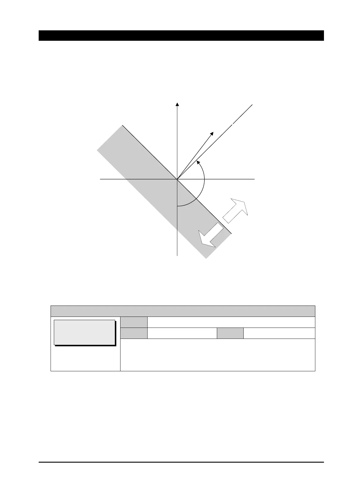
The following diagram shows the phasor diagram for I
g
directional polarization in the complex
plane.
Figure 7-9. Phasor Diagram for I
g
Directional Polarization
The ground direction control in the following four settings should be enabled.
PRIMARY SETTING / PROTECTION / DIRECTION / GROUND DIRECTION / Type
Range
OFF, FOR, REV
Default
OFF
Step
~
OFF : None direction
FOR : Forward direction
REV : Reverse direction
Maxim
um
To
r
q
ue Li
n
e
-V0
Zero T
o
r
q
ue L
ine
F
orward
Reverse
Ig
V0
Polarizing Referance
Voltage:
Fault Current
[GROUND DIRECTION]
>Type: OFF
M.T.A: 135
M.P.V: 0.20