RECLOSER CONTROL EVRC2A-N6,NT http://www.entecene.co.kr
296
ENHANCED
TECHNOLOGY
14.2. Malfunction Events
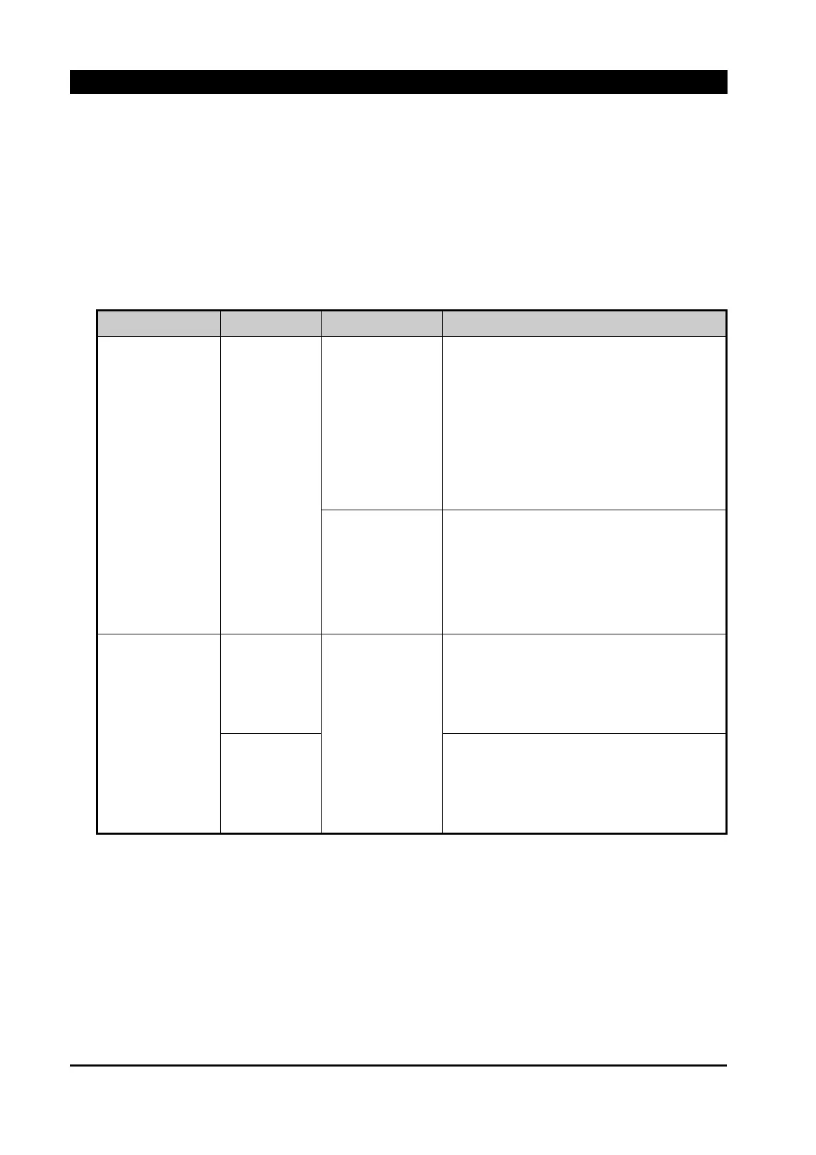
The following table of events describes the malfunction events available from the control and
what they indicate. It also suggests steps to follow to assist in determining why the event was
generated.
Table 14-2. Malfunction Events
EVENT DESCRIPTION POSSIBLE CAUSE RECOMMENDED ACTION
OPERATION FAIL Operation Fail
Control Cable
1 Connection state of control cable
2. control Box inside CN8 connection state check
- Table 13-2 - Figure 13-8 - Figure 13-9
- Figure 13-10 - Figure 13-15 Reference
3. control Box inside CN6 connection state check
- Figure 13-8 - Figure 13-9
- Figure 13-10 Reference
Etc..
1.That control switch point of contact check
2. control Box inside FUSE state check
- Figure 13-31 Reference
3. Replace Relay Module
4. Replace Recloser
Fail of current &
voltage measurement
Current measure
Control Cable
1 Connection state of control cable
2. control Box inside CN1 connection state check
- Table 13-2 - Figure 13-8 - Figure 13-9
- Figure 13-10 - Figure 13-15 Reference
Voltage measure
1 Connection state of control cable
2. control Box inside CN2 connection state check
- Table 13-2 - Figure 13-8 - Figure 13-9
- Figure 13-10 - Figure 13-15 Reference