RECLOSER CONTROL EVRC2A-N6,NT http://www.entecene.co.kr
289
ENHANCED
TECHNOLOGY
13.34. Recloser Current Transformer (CT)
Table 13-9. Current Transformer (CT)
Description Pin Function
CT Ratio : (1000:1/standard)
CT Resistance < 5Ω
A C.T Phase C
B C.T Phase B
C C.T Phase A
D C.T Common(G)
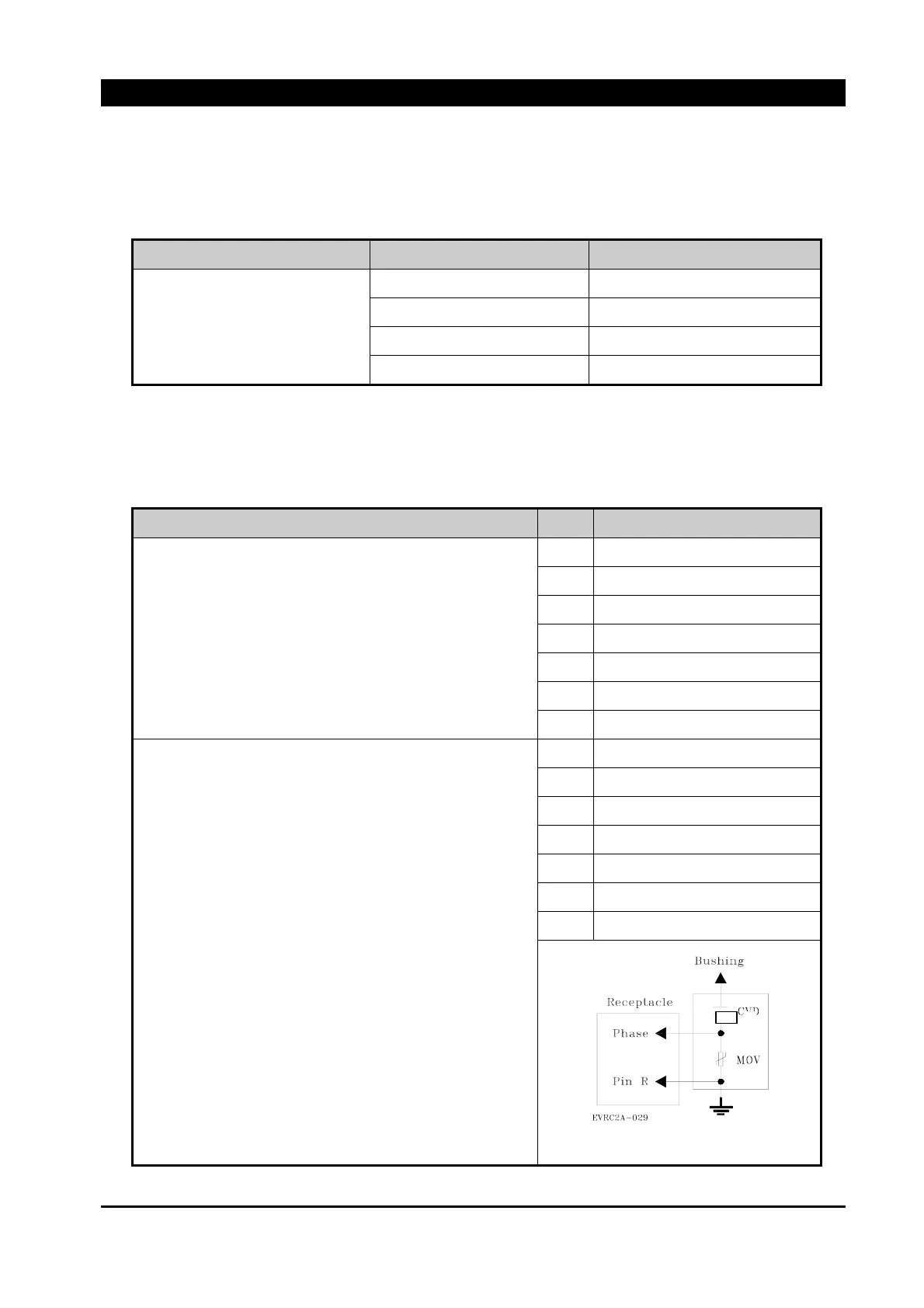
13.35. Recloser Voltage Divider (VD)
Table 13-10. Capacitor Voltage Divider (VD)
Description Pin Function
EVR RECLOSER
1) Pin R is connected to Ground.
2) CVD Capacitance : 20㎊
3) For CVD Protection, MOV is connected between
Phase and Ground.
E CVD Source Phase C
F CVD Source Phase B
G CVD Source Phase A
H CVD Load side Phase T
J CVD Load side Phase S
K CVD Load side Phase R
R Cable shield and Ground
EPR RECLOSER
1) Pin R is connected to Ground.
2) RVD Resistance : 10MΩ
3) For RVD Protection, MOV is connected between
Phase and Ground.
y For voltage measuring, use High Impedance AC
Voltmeter(Digital Multimeter) at Output Pin.
y Voltage Measuring Method 1
measure MOV voltage.
(measure a voltage between MOV arms)
y Voltage Measuring Method 2
Place the capacitor(C2) in parallel with MOV. and
measure MOV voltage.
E RVD Source Phase C
F RVD Source Phase B
G RVD Source Phase A
H CVD Load side Phase T
J CVD Load side Phase S
K CVD Load side Phase R
R Cable shield and Ground
Figure 13-34. VD Wiring Diagram