RECLOSER CONTROL EVRC2A-N6,NT http://www.entecene.co.kr
269
ENHANCED
TECHNOLOGY
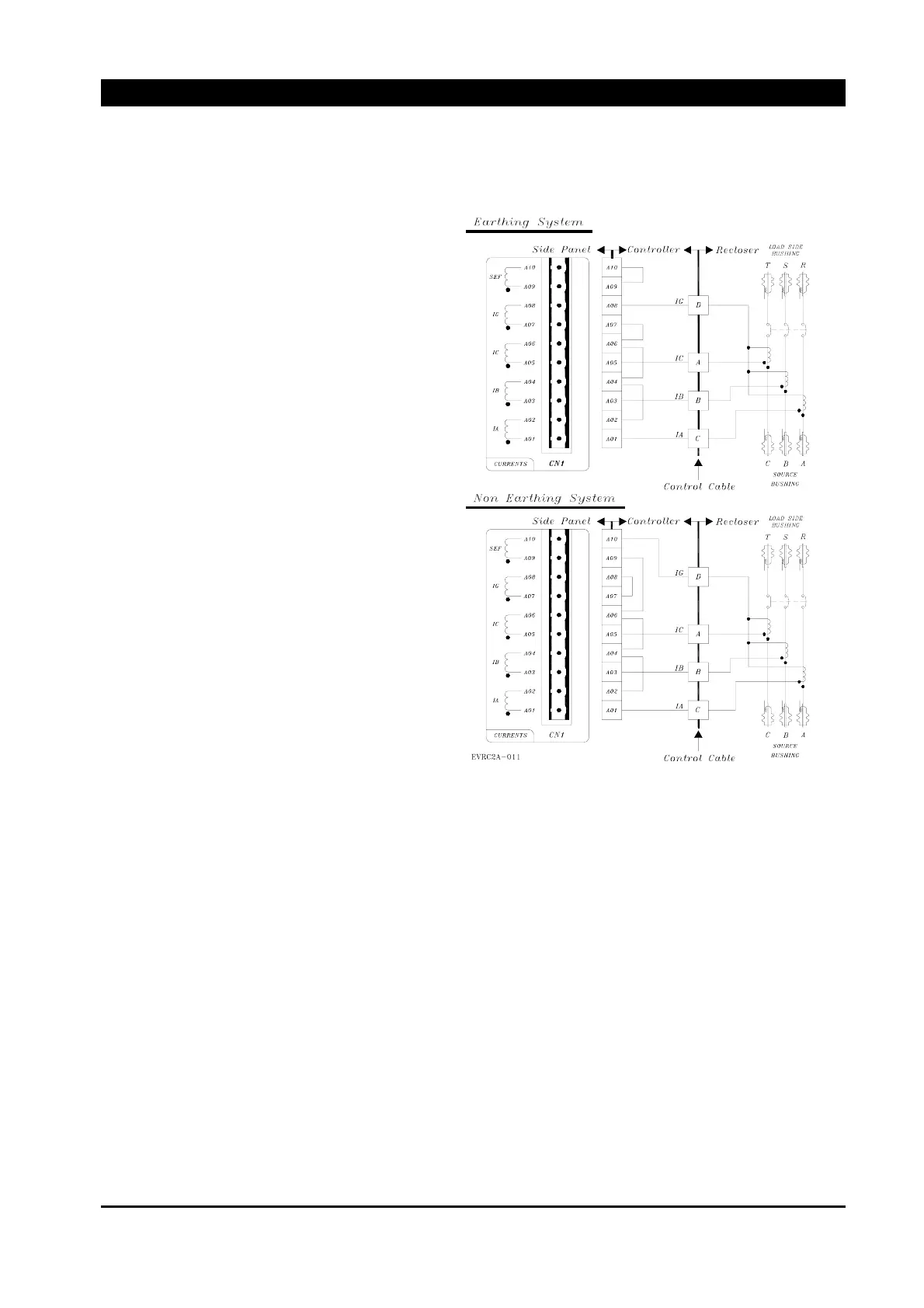
13.12. Current Inputs Wiring Diagram
Current IG is connected with Side Panel
IG(A07,A08) in Earthing System.
SEF(A09,A10) should be connected, so
called “JUMPER”
IG Input Current Range
y 0.5A Nominal
y 2A continuous
y 25A 1 second
y Burden : 0.19VA(0.5A)
Current IG should be connected with
SEF(A09,A10) of Side Panel in.
Non Earthing System.
IG(A07,A08) should be connected to each
other.
SEF Input Current Range
y 0.05A Nominal
y 0.16A Continuous
y 0.6A 1 second
y Burden : 0.0375VA(0.05A)
Figure 13-11. Current Inputs Wiring Diagram
Recloser Phase should match with User system. Refer to “Figure 13-14. Phase Rotation”
CT Phase rotation must be arranged comparing with Voltage Inputs Phase rotation.
 Loading...