C8-B/C12-B Service Manual Adjustment Disclosure Scope: Maintenance Trained Personnel Only
(C) Seiko Epson Corporation 3-12 Rev.1
When the home positions of the Joints #1 and #4 are uncertain, check torsion of the internal cables. The home positions
are where the Manipulator has the internal cables not twisted at the basic orientation described in C-B series Manual C8
Manipulator 3.3.6 Checking the Basic orientation, C-B series Manual C12 Manipulator 4.3.6 Checking the Basic
orientation.
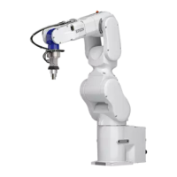
Torsion of the internal cables can be checked by removing the following covers.
Joint #1 : Base cover (Cable backward model), Connecter plate (Cable downward model)
Joint #4 : Arm #3 cover (common between cable downward and cable backward models)
For details on Jog & Teach, refer to the following manual.
EPSON RC+ User’s Guide
⚫ For details about the basic orientation, refer to C-B series Manual C8 Manipulator 3.3.6 Checking the Basic orientation,
C-B series Manual C12 Manipulator 4.3.6 Checking the Basic orientation.
⚫ Whenever possible, calibrate one joint at a time. (Also, replace parts of one joint at a time whenever possible.) If you
calibrate the origins for multiple joints simultaneously, it will be more difficult to verify their origins and obtain the origin
correct positions.
However, joint #5 cannot be calibrated alone due to the structure of the Manipulator. Make sure you calibrate joint #5
and #6 at the same time.