L1800 Revision A
Disassembly And Assembly Disassembling the Printer Mechanism 72
Confidential
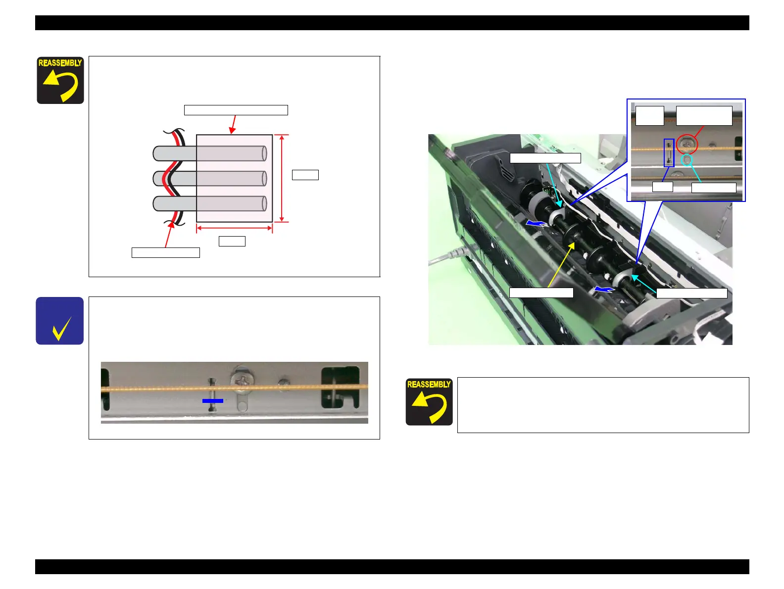
9. Remove the two C.B. M3 x 6 screws that secure the two Guide Roller LDs.
10. Gently pull the LD Roller Shaft to the rear of the printer, and remove the Guide
Roller LDs.
Figure 3-86. Removing the Guide Roller LD
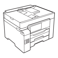
Referring to Figure 3-83, correctly route each of the cables and
FFCs.
Apply the acetate tape A according to the standard below.
Figure 3-84. Applying the Acetate tape A
When only removing the ASF Assy, you do not need to perform
"4.3.5 ASF Guide Roller LDs Position Adjustment (p131)". In that
case, mark the installing positions of the Guide Roller LDs before
removing them, and make sure to align the markings when
installing the Guide Roller LDs.
Figure 3-85. Marking Position
APG Motor cable
Acetate tape A (18 x 13 mm)
5 mm
18 mm
Align the guide pins and tabs on the Guide Roller LDs with the
positioning holes on the Main Frame. (Refer to Figure 3-86.)
Front
Face
17) C.B. M3x6
(8±1 kgf.cm)
Guide pin
Tab
LD Roller Shaft
Guide Roller LD
Guide Roller LD

 Loading...