EPSON Stylus
COLOR
1520
Rev. A
4-
4.1.5 Color Head Angular Adjustment
You must make this adjustment when replacing or disassembling the color head. The color head is, same
as black head, held by the compression spring to the supporting point of the CR unit and the angle adjust
lever located under the color head. The adjust lever is used to swing the color head in parallel to the
printing surface. With this operation, the YMC heads are set at a proper angle.
1. Connect the printer and the host computer with a parallel interface cable.
2. Start the adjustment program in the host computer.
3. Input the customer data. (Refer to Section 4.1.2.)
4. Move the cursor using
or
key to select “ADJUST” in the 1st menu. Then press the Enter key, and
the main menu appears on the monitor.
5. Move the cursor using
or
key to select “HEAD ANGULAR ADJUSTMENT”. Then press the Enter key,
and the printer prints out the head angular adjustment patterns.
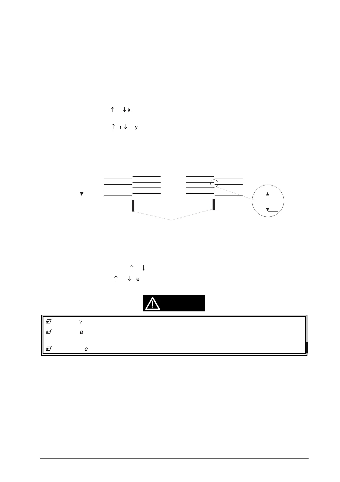
6. Move the angle adjust lever to make the deviation (B) between 2 colors less than 4/1 of the line
width.
(Refer to Figure 4-6.)
7. Press the Space key to repeat the operation. Press the Enter key to exit “Color Head Angular
Adjustment”, and the main menu appears.
8. Select other adjustment using
or
key, or select “RETURN TO 1st MENU” to exit the main menu.
9. Move the cursor using
or
key to select “END” and press the Enter key to exit the adjustment
program.
While moving the angle adjust lever, lift it up a little.
Ensure that the lever does not move by fitting the notches in the lever to the location holes on the
CR unit securely.
Do not move the lever with much force, since it is breakable.
Move the lever right.
Move the lever left.
Paper feed direction
Gaps between colors
(B)
Figure 4-6. Color Head Angular Adjustment
CAUTION

 Loading...


