EasyManuals Logo

Epson Stylus Color 1520 Service Manual

Epson Stylus Color 1520
165 pages
To Next Page IconTo Next Page
To Previous Page IconTo Previous Page
Page #95 background imageLoading...
Page #95 background image
EPSON Stylus
COLOR
1520
Rev. A
3-2
4
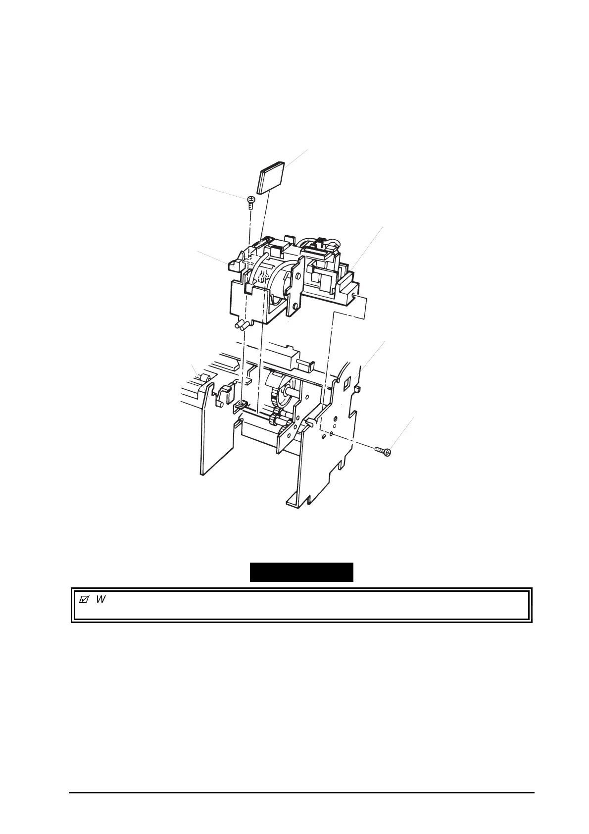
3.2.10.8 Pump Unit Removal
1. Remove the printer mechanism unit. (Refer to Section 3.2.6.)
2. Remove the paper eject frame. (Refer to Section 3.2.10.7.)
3. Remove 2 screws (CBS, 3X6 and CBP, 3X8) securing the pump unit to the printer mechanism unit.
Then remove the pump unit.
When mounting the head cleaner onto the pump unit, set the rubber part of the cleaner facing to
the pump side.
Head Cleaner
Pump Unit
Right Frame Assembly
Screw (CBP 3X8)
Middle Frame Assembly
Head Cleaner Lever
Screw (CBS 3X6)
Figure 3-21. Pump Unit Removal
WORK POINT

Table of Contents

Other manuals for Epson Stylus Color 1520

Questions and Answers:

Question and Answer IconNeed help?

Do you have a question about the Epson Stylus Color 1520 and is the answer not in the manual?

Epson Stylus Color 1520 Specifications

General IconGeneral
ColorYes
Maximum resolution600 x 1200 DPI
Print speed (black, normal quality, A4/US Letter)- ppm
Maximum input capacity100 sheets
Envelopes sizes10, C5, DL
Standard media sizes4\
Paper tray media typesEnvelopes, Labels, Plain paper
Non-ISO print media sizesLegal
ISO A-series sizes (A0...A9)A4
ISO B-series sizes (B0...B9)B5
Power requirements120V AC, 50/60 Hz
Printing noise level45 dB
Maximum operating temperature range (T-T)-20 - 60 °C
Market positioningHome & office

Related product manuals