EasyManuals Logo

Epson Stylus Color 1520 Service Manual

Epson Stylus Color 1520
165 pages
To Next Page IconTo Next Page
To Previous Page IconTo Previous Page
Page #142 background imageLoading...
Page #142 background image
EPSON
Stylus
COLOR
1520
Rev. A
A-
2
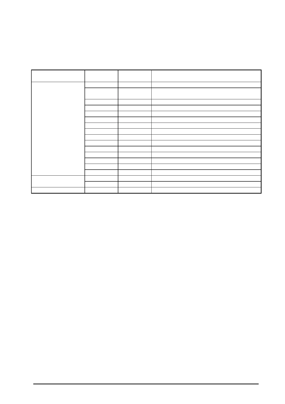
A.1.1 Connector Pin Assignment
Table A-1 shows the locations an descriptions for the connectors on the circuit boards in this printer.
Table from A-2 to A-13 show the pin assignment for each connector.
Circuit Board Connector
No.
Pin No. Description
CN1 8 Mac Serial I/F (Refer to Section 1.3.3.)
CN2 9 DC input from the C172 PSB/PSE board
Power off signal
CN3 3 HP sensor
CN4 2 DE sensor
CN5 36 Type-B I/F (Refer to Section 1.3.4.)
CN6 36 Parallel I/F (Refer to Section 1.3.1 and 1.3.2.)
C211 MAIN-B Board CN7 20 C211 PNL Board
CN8 2 Release sensor
CN9 2 Cover open sensor
CN10 2 Front PE sensor
CN11 2 Rear PE sensor
CN12 24 Color head
CN13 22 Black head
CN14 5 CR motor
CN15 4 PF motor
C172 PSB/PSE Board CN1 2 AC power input
CN2 9 DC power input
C172 PNL Board CN1 20 To C211 MAIN-B board
Table A-1. Connector Summary

Table of Contents

Other manuals for Epson Stylus Color 1520

Questions and Answers:

Question and Answer IconNeed help?

Do you have a question about the Epson Stylus Color 1520 and is the answer not in the manual?

Epson Stylus Color 1520 Specifications

General IconGeneral
ColorYes
Maximum resolution600 x 1200 DPI
Print speed (black, normal quality, A4/US Letter)- ppm
Maximum input capacity100 sheets
Envelopes sizes10, C5, DL
Standard media sizes4\
Paper tray media typesEnvelopes, Labels, Plain paper
Non-ISO print media sizesLegal
ISO A-series sizes (A0...A9)A4
ISO B-series sizes (B0...B9)B5
Power requirements120V AC, 50/60 Hz
Printing noise level45 dB
Maximum operating temperature range (T-T)-20 - 60 °C
Market positioningHome & office

Related product manuals