EasyManuals Logo

Epson Stylus Color 1520 Service Manual

Epson Stylus Color 1520
165 pages
To Next Page IconTo Next Page
To Previous Page IconTo Previous Page
Page #40 background imageLoading...
Page #40 background image
EPSON Stylus COLOR 1520
Rev. A
1-3
2
1.6 Main Components
The main components of the EPSON Stylus COLOR 1520 are designed for easy removal and repair.
They are as follows:
Main control board :C211 MAIN Board
Power supply board :C172 PSB/PSE Board
Control panel bard
Printer mechanism :M-4160
Housing
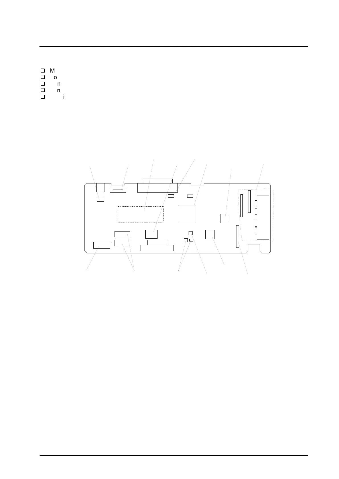
1.6.1 C211 MAIN Board
This board consists of a 16-bit CPU (IC7) (clock wave : 19.66Mhz), gate arrays B05B33 (IC8) and
B05B34 (IC6), PROM (IC14), MROM (IC12), DRAMs (IC9, 10), RESET ICs (IC1, 4), EEPROM (IC2), two
motor drive ICs, printhead drive circuit, and so on.
Gate Array E05B33CPULithium Battery
Gate Array E05B34
PROM 8M
DRAM 4M
MROM
Reset IC
EEPROM
Timer IC
PF Motor Drive IC
CR Motor Drive IC
Printhead Common Drive Circuit
Serial Interface IC
Figure 1-13. C211 MAIN Board Component Layout

Table of Contents

Other manuals for Epson Stylus Color 1520

Questions and Answers:

Question and Answer IconNeed help?

Do you have a question about the Epson Stylus Color 1520 and is the answer not in the manual?

Epson Stylus Color 1520 Specifications

General IconGeneral
ColorYes
Maximum resolution600 x 1200 DPI
Print speed (black, normal quality, A4/US Letter)- ppm
Maximum input capacity100 sheets
Envelopes sizes10, C5, DL
Standard media sizes4\
Paper tray media typesEnvelopes, Labels, Plain paper
Non-ISO print media sizesLegal
ISO A-series sizes (A0...A9)A4
ISO B-series sizes (B0...B9)B5
Power requirements120V AC, 50/60 Hz
Printing noise level45 dB
Maximum operating temperature range (T-T)-20 - 60 °C
Market positioningHome & office

Related product manuals