Product Description
Rev. A
1-1
1.3.1.2 Reverse Channel Specifications
Transmission mode :IEEE-1284 nibble mode
Adaptable connector :Same as for the forward channel
Synchronization :Refer to the IEEE-1284 specification
Handshaking :Refer to the IEEE-1284 specification
Data transmission timing :Refer to the IEEE-1284 specification
Signal level :IEEE-1284 level 1 device
See the forward channel specification.
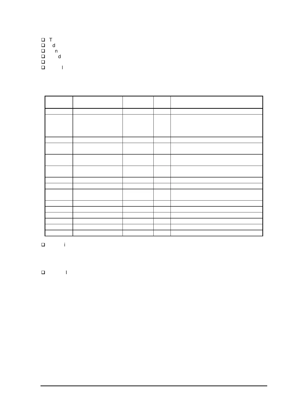
Table 1-18 shows the connector pin assignment and signals for reverse channel of the parallel interface.
Pin No. Signal Name Return
GND Pin
I/O Description
1 HostClk 19 I Clock signal from the host computer.
2-9 DATA 0-7 20-27 I These signals represent parallel data
information on bits 2 to 9.Each signal is
High when the data is logical 1 and low
when the data is logical 0.
10 PtrClk 28 O Clock signal from the printer
11 PtrBusy /
Data bits 3,7
29 O Busy signal from the printer.
Data bit 3 or 7 in reverse channel.
12 AckDatareq /
AckData Bits 2,6
28 O Acknowledge request signal.
Data bit 2 or 6 in reverse channel.
13 Xflag/Data bit 1,5 28 O X flag signal.
Data bit 1 or 5 in reverse channel.
14 HostBusy 30 I Busy signal from the host computer
31 /INIT 30 I Not used
32 /Data Avail /
Data bits 0,4
29 O Data available signal.
Data bit 0 or 4 in reverse channel.
36 1284-Active 30 I 1284 active signal.
18 Logic-H - O Pulled up to +5V via 3.9 K ohm resistor.
35 +5V - O Pulled up to +5V via 3.3 K ohm resistor.
17 Chassis GND - - Chassis ground for the printer.
16,33,19-30 GND - - Signalground.
15,34 NC - - Not connected.
Note) The symbol */* at the beginning of a signal means active low.
Extensibility Request
The printer responds affirmatively when the extensibility request values are 00H or 04H, as follows:
00H :Request Nibble Mode Reverse Channel Transfer.
04H :Request Device ID;
Return Data Using Nibble Mode Rev Channel Transfer.
Device ID
The printer sends following device ID string when it is requested.
[00H] [xxH]
MFG :EPSON;
CMD :ESCP2E, PRPXL;
MDL :Stylus COLOR 1520;
CLS :PRINTER
Note) [00H] denotes a hexadecimal values of zero.
Table 1-18. Connector Pin Assignment and Signals (Reverse Channel)

 Loading...


