EPSON Stylus
COLOR
1520
Rev. A
2-1
2.3.2 C211 MAIN Control Board
This printer uses C211 MAIN for the main control circuit board. It consists of the following:
16-bit CPU C90A02CB (IC7) :Running at 19.66 MHz
2 gate arrays E05B33 (IC6) :Controls interfaces, motors and printheads.
E05B34 (IC5)
P-ROM, DRAM and MROM
Drivers :Produces common voltage for the motors and printheads.
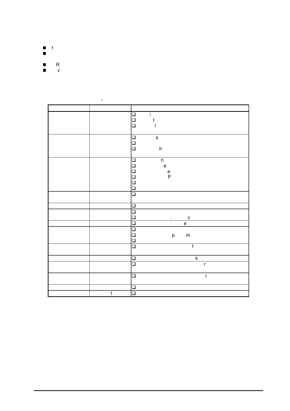
Table 2-8 and Figure 2-19 show the allocated functions for major components and the main control
circuit block diagram, respectively.
IC Location Function
CPU IC7
16-bit CPU
Run at 19.66 MHz
Controls the printer at the gate arrays IC5 and
IC6 according to the program in P-ROM.
Gate Array IC5
Controls the I/F for the control panel.
Controls the CR motor.
Detects the signals from the PE sensor, cover
open sensor and REL (Release) sensor.
Gate Array IC6
Controls the parallel I/F.
Controls the serial I/F.
Controls Type-B I/F.
Controls the PF motor.
Controls black and color heads.
Controls the HP sensor and DE sensor.
DRAM IC9
Manages buffers, work area in the CPU, and
stuck area.
DRAM IC10
For image buffer. Expansion
MROM IC13
24 Mbit
Manages C.G. (Character Generator).
P-ROM IC11
Equipped only for the European version.
P-ROM IC14
8Mbit
Printer control program
Manages C.G. (Character Generator).
EEPROM IC2
Stores values for the default settings and other
values.
Timer counter IC IC3
Manages timers for the ink system.
Common driver
IC
IC18
Produces common voltage for the black head.
Common driver
IC
IC19
Produces common voltage f or the color head.
Driver IC16
Drives the PF motor.
Driver IC17
Drives the CR motor.
Table 2-8. Location and function of the Major Components

 Loading...


