EPSON Stylus COLOR 1520
Rev. A
1-1
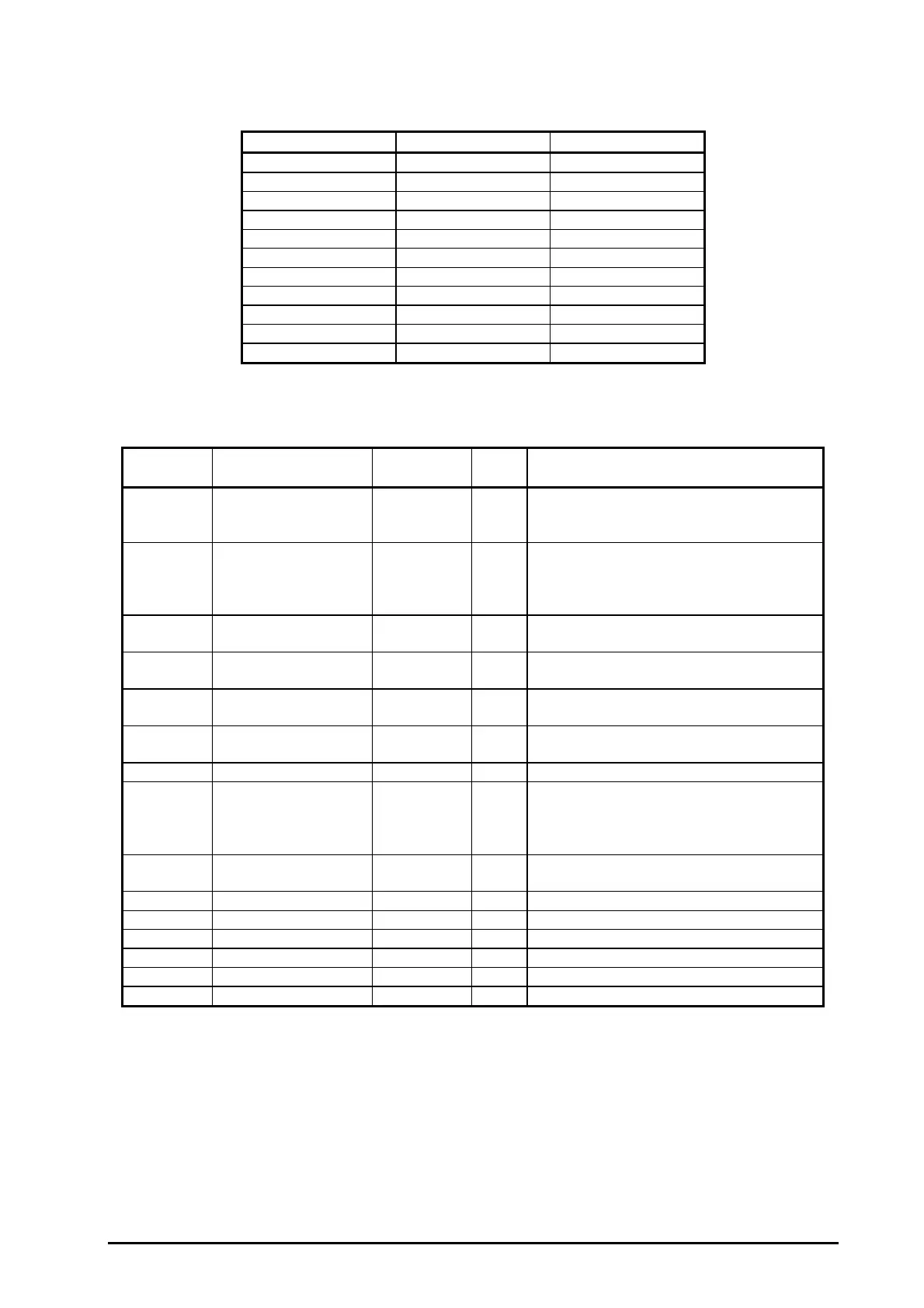
Table 1-16 shows the connector pin assignment and signals for forward channel of the parallel interface.
Parameter Minimum Maximum
tsetup 500 ns -
thold 500 ns -
tstb 500 ns -
tready 0 -
tbusy - 500 ns
tt-out* - 120 ns
tt-in** - 200 ns
treply - -
tack 500 ns 10 us
tnbusy 0 -
tnext 0 -
Note) * : Rises and falls in time of every output signals.
**: Rises and falls in time of every input signal.
Pin No. Signal Name Return
GND Pin
I/O Description
1 /STROBE 19 I
The strobe pulse. Read-in of data is
performed at the falling edge of this
pulse.
2-9 DATA 0-9 20-27 I
The data 0 to data 7 signals represent
data bits 0 to 7, respectively. Each signal
is at high level when data is logical 1 and
low level when data is logical 0.
10 /ACKNLG 28 O This signal is a negative pulse indicating
that the printer can again accept data.
11 BUSY 29 O When this signal is at high level, the
printer is not ready to accept data.
12 PE 28 O When this sign is at high level, the paper
empty status is detected.
13 SLCT 28 O Always at high level when the printer is
powered on.
14 /AFXT 30 I Not used.
31 /INIT 30 I The falling edge of a negative pulse or a
low signal on this line causes the printer
to initialize. Minimum 50 us pulse is
necessary.
32 /ERROR 29 O When the printer detects an error, this
signal goes low.
36 /SLIN 30 I Not used.
18 Logic H - O Pulled up to +5V via 3.9 K ohm resistor.
35 +5V - O Pulled up to +5V via 3.3 K ohm resistor.
17 Chassis GND - - Chassis ground.
16,33,19-30 GND - - Signal ground.
15,34 NC - - Not connected.
Note) 1. */* at the beginning of a signal means active low.
2. The I/O column indicates the diction of the signal as viewed form the printer.
Table 1-16. Data Transmission Timing
Table 1-17. Connector Pin Assignments and Signals (Forward Channel)

 Loading...


