EasyManuals Logo

Epson Stylus Color 1520 Service Manual

Epson Stylus Color 1520
165 pages
To Next Page IconTo Next Page
To Previous Page IconTo Previous Page
Page #88 background imageLoading...
Page #88 background image
Disassembly and Assembly
Rev. A
3-1
7
When mounting the CR motor, make sure that the connector cable for the DE (disengage) sensor
doesn’t cut in.
CR fan motor and the CR motor assembly are 2 different parts. Therefore be sure to attach the
CR fan motor when replacing the CR motor assembly. Use the specified adhesive to attach the
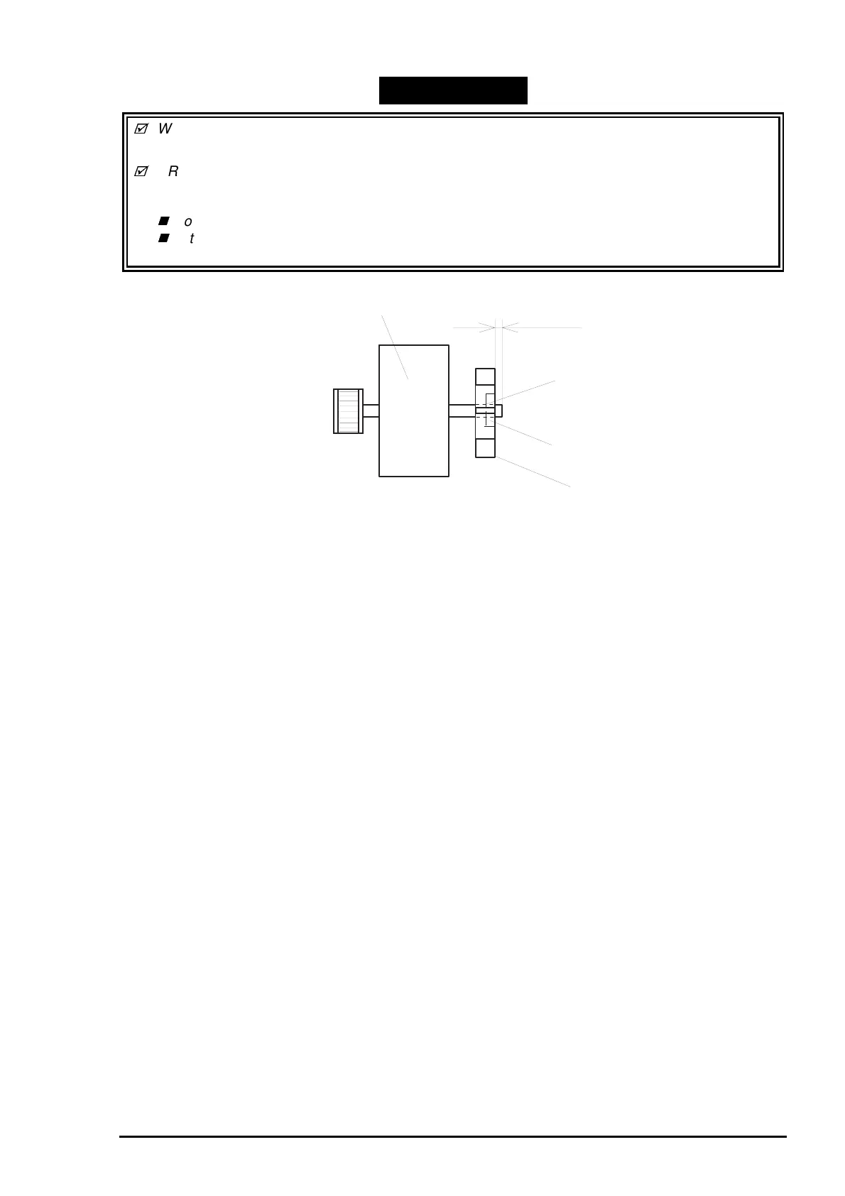
fan to the motor shaft. (Refer to Chapter 6.) Note the following when attaching the fan:
Do not insert the fan more than 1 mm from the shaft end.
Set the fan with the indented side facing outward.
(Refer to Chapter 6.)
WORK POINT
CR Motor Assembly
Adhesive
(A) : 1 mm or less
Indented Side
Fan
Figure 3-13. Fixing the CR Motor Fan

Table of Contents

Other manuals for Epson Stylus Color 1520

Questions and Answers:

Question and Answer IconNeed help?

Do you have a question about the Epson Stylus Color 1520 and is the answer not in the manual?

Epson Stylus Color 1520 Specifications

General IconGeneral
ColorYes
Maximum resolution600 x 1200 DPI
Print speed (black, normal quality, A4/US Letter)- ppm
Maximum input capacity100 sheets
Envelopes sizes10, C5, DL
Standard media sizes4\
Paper tray media typesEnvelopes, Labels, Plain paper
Non-ISO print media sizesLegal
ISO A-series sizes (A0...A9)A4
ISO B-series sizes (B0...B9)B5
Power requirements120V AC, 50/60 Hz
Printing noise level45 dB
Maximum operating temperature range (T-T)-20 - 60 °C
Market positioningHome & office

Related product manuals