EPSON Stylus COLOR 440, 640, and 740 Appendix
148
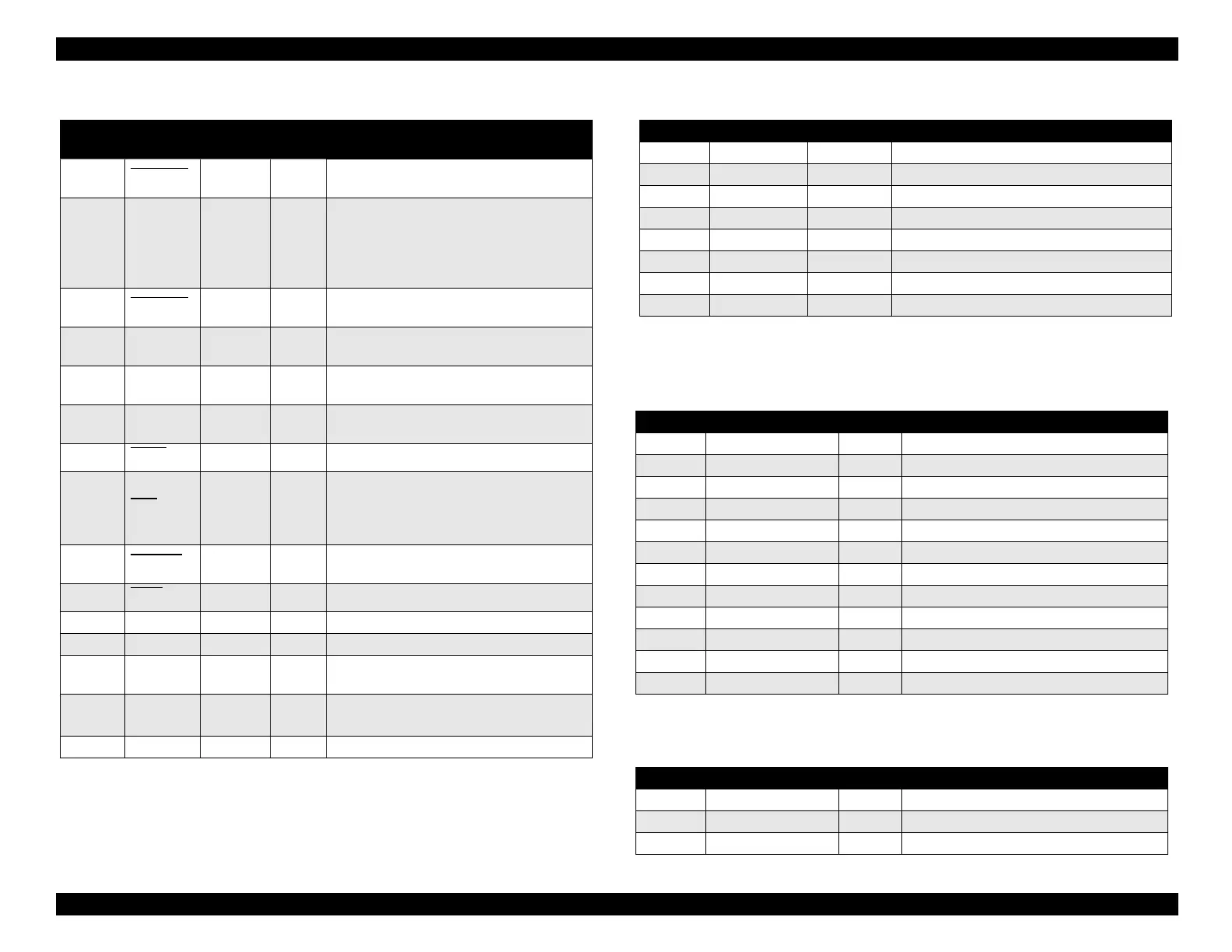
Table A-2. Parallel Interface Connector (CN1) Table A-3. Serial Interface Connector (CN2)
Pin No.
Signal
Name
Return
GND Pin
In/Out Functional Description
1STROBE
19 In
The strobe pulse. Data is read in at the
falling edge of this pulse.
2 to 9
DATA0 to
DATA7
20 to 27 In
The DATA0 through DATA7 signals
represent data bits 0 through 7. Each
signal is at a HIGH level when data is
logical 1, and at a LOW level when data
is logical 0.
10 ACKNLG
28 Out
This signal is a negative pulse indicating
that the printer can again accept data.
11 BUSY 29 Out
A HIGH signal indicates that the printer
cannot receive data.
12 PE 28 Out
A HIGH signal indicates a paper-out
error.
13 SLCT 28 Out
Always HIGH when the printer is
powered on.
14 AFXT
30 In Not used.
31 INIT 30 In
The falling edge of a negative pulse or a
LOW signal on this line causes the
printer to initialize. Minimum 50
µ
s pulse
is necessary.
32 ERROR
29 Out
A LOW signal indicates a printer error
condition.
36 SLIN 30 In Not used.
18 Logic-H — Out Pulled up to +5 V via 3.9K ohm resistor.
35 +5V — Out Pulled up to +5 V via 3.3K ohm resistor.
17
Chassis
GND
— — Chassis ground.
16, 33,
19 to 30
GND — — Signal ground.
15, 34 NC — — Not connected.
Notes: In and Out refer to the direction of signal flow from the printer’s point of view.
A slash in front of a signal name means that the signal is active LOW.
Pin No. Signal Name I/O Functional Description
1 SCLK Out Synchronous clock signal
2 CTS In Clear To Send
3 TXD- Out Transmit Data (-)
4 SG In Signal Ground
5 RXD- In Receive Data (-)
6 TXD+ Out Balanced Transmit Data (+)
7 DTR Out Data Terminal Ready
8 RXD+ In Balanced Receive Data (+)
Table A-4. Control Panel Connector (CN3)
Pin Signal Name I/O Function
1 LED0 Out LED drive signal (0)
2 GND — Ground
3 LED1 Out LED drive signal (1)
4 GND — Ground
5 LED2 Out LED drive signal (2)
6 +5 V — Logic power supply
7 +5 V — Logic power supply
8 LED4 Out LED drive signal (4)
9 SW1 In Panel switch input (1)
10 PSC In Power on/off switch
11 SW0 In Panel switch on/off (0)
12 SW2 In Panel switch on/off (2)
Table A-5. PE Sensor Connector (CN4)
Pin Signal Name I/O Function
1 PE In Sensor detect signal
2 GND — Ground
3 PEV — Sensor power supply (+5 V)
 Loading...


