EPSON Stylus COLOR 440, 640, and 740 Chapter 2 Operating Principles
49
2.2.1 Power Supply Board
The St
lus COLOR 440, 640, and 740 use one of two power suppl
boards: the PSB, which accepts 120 volts, or the PSE, which accepts
240 volts. The difference between them lies in their primar
circuitr
,
which includes the power line filter, the main switchin
transistor, and
the transformer. In the PSE, these components are desi
ned to
withstand hi
her input volta
es than in the PSB. Except for these
differences, the two boards are exactl
the same.
The power suppl
provides filtered output at 5 and 42 VDC. These
volta
es power the various printer functions shown in the table below.
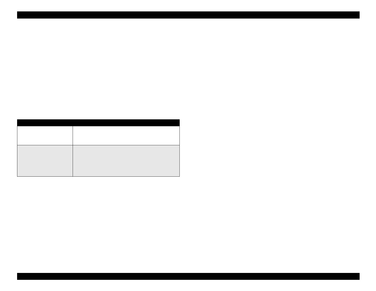
Table 2-8. Power Output Applications
Built into the power suppl
is a dela
circuit, which keeps the printer full
powered for about 30 seconds after the printer is turned off.
This works
onl
when
ou turn the power off b
pressin
the Power switch on the
front control panel; the printer will
not
sta
on if
ou unplu
it.
The
dela
ives the printer time to e
ect an
paper that ma
be in the paper
path and to return the carria
e to its home position.
The carria
e must
return to its home position in order to cap the printhead. If the printhead
remains uncapped, ink dries out and clo
s the printhead.
Power Supply Operation
When the printer is plu
ed in, electricit
is alwa
s present in the
primar
circuitr
of the power suppl
. This means that certain
components are alwa
s “hot,” includin
the power line filter circuit, the
main switchin
transistor, and the transformer. Note that the heat sink
on the main swtichin
transistor
Q1
is
not
electricall
isolated. Never
touch the primar
components of the power suppl
with the printer
plu
ed in.
The secondar
power suppl
circuitr
, as well as the rest of the printer’s
electrical components, are electricall
isolated from the primar
power-
line volta
e. Isolation is accomplished b
transformer T1 and photo-
coupler PC1.
The power suppl
consists of a line filter, a ZC-RCC
Zero-Cross
Rin
in
Choke Converter
switchin
circuit, and a 5-volt chopper
re
ulator IC. See Fi
ure 2-16. When AC power enters the printer from
an external power source, the line filter blocks power-line transients
from enterin
the printer and prevents radio fre
uenc
interference
hi
h-level harmonics
enerated b
the switchin
circuit from bein
placed back onto the power line. In the PSB board, the primar
current
at 120 VAC rms
then under
oes full-wave rectification and is
smoothed to produce 160 VDC.
In the PSE board, the 220 VAC input
is over 300 VDC after filterin
.
This is fed throu
h the RCC switchin
circuit and a secondar
smoothin
circuit to produce a stepped-down 42
VDC; feedback ensures stable output. A second, additional output at 5
VDC is produced b
a chopper re
ulator IC which draws from the 42-
volt suppl
.
At the heart of the switchin
circuit is a power MOSFET
Q1
, an
efficient t
pe of transistor that dissipates relativel
little heat. B
usin
a
transistorized switchin
circuit instead of a transformer to re
ulate
Voltage Application
42 VDC CR motor
PF motor
Printhead PZTs
5 VDC Logic circuitry
Control signals
Sensors
Control panel LEDs
Printhead nozzle selector IC
 Loading...


