EPSON Stylus COLOR 440, 640, and 740 Chapter 2 Operating Principles
58
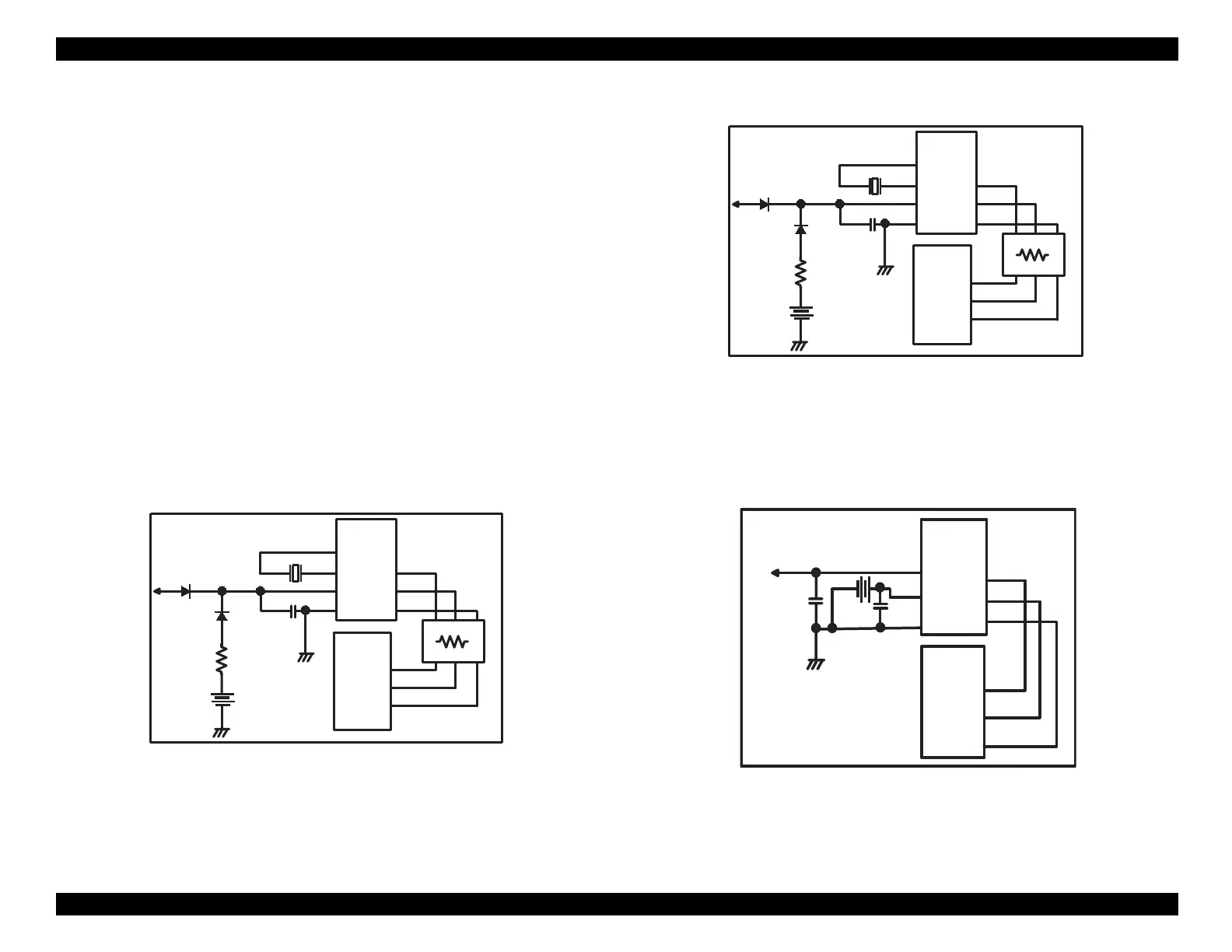
Power-Off Timer Circuit
The timer IC measures how lon
the printer is turned off. When the
printer is turned on, the IC sends the power-off time to the
ate arra
.
The power-off time determines how extensivel
the printhead is cleaned
at power-on.
In the St
lus COLOR 440 and 640, an external cr
stal oscillator
CR1 or
CR3
provides the basic timin
pulse. In the St
lus COLOR 740, the
oscillator is built into IC8, the same chip that contains the reset circuit.
Since the cr
stal’s oscillation produces an analo
waveform, the timer
IC converts it into a s
uare wave to enable it to be processed di
itall
.
When the printer is on, power is supplied to the timer throu
h the 5-volt
power bus. When the printer is turned off, a 3-volt lithium batter
powers the chip. Diodes on the power suppl
line prevent the batter
from char
in
when the printer is on, and from dischar
in
back into the
power line when the printer is off.
Figure 2-26. Timer Control Circuit for Stylus COLOR 440
Figure 2-27. Timer Counter Circuit for Stylus COLOR 640
Figure 2-28. Timer Counter Circuit for Stylus COLOR 740
+5
Batt1
D7
D1
C4
0.1u
S-3510ANF
(IC5)
XI
XO
2
3
VCC
GND
8
4
5
6
7
123
121
124
CR1
E05B44
(IC2)
TCE
TCLK
TDATA
RM7
CS
/SCK
/SIO
+5
Batt1
D1
D4
C4
0.1u
S-3510ANF
(IC10)
XI
XO
2
3
VCC
GND
8
4
5
6
7
125
123
126
CR3
E05B43
(IC2)
TCE
TCLK
TDATA
RM7
CS
/SCK
/SIO
RTC-9810
(IC 8 )
Vin
9
7
8
5
6
4
CE
SCLK
Data
Vdd
Vbk
GND
20
21
23
E05B 588
(IC 2 )
T M C S
T M C K
TM D ATA
+5
14
Batt1
 Loading...


